background image

page 5

595 ML CRL (S)

800-00177

ABBREVIATIONS AND SYMBOLS

EXPLANATIONS OF OTHER OCCURRENCES IN THIS MANUAL:

-

In a parts list, when there are item numbers with empty spaces (no description or part number), these
parts  have been previously deleted from that parts list and are not recorded anywhere.

-

In a parts list, when there are items with no part number and a dotted line (----) is in the part number
space, this means that the part number is not sold separately or is not available at this time.

-

When references to "right hand" or  "left hand" are used in this manual, it is done from the operator's seat
in the forward operating position.

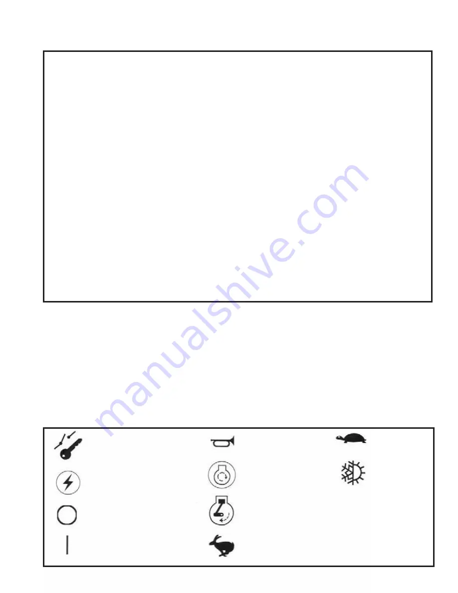
SYMBOLS USED ON MACHINE

Ignition
Key Switch

Power On
(Accessory)

Power Off

Power On

Horn

Starter

Engine RPM

Faster

Slower

Air
Conditioner

a/c

=

air conditioner

AC

=

Articulated Carrier (Art. Car.)

adj.

=

adjust or adjusting

appl.

=

application

AR

=

As Required

assy

=

assembly

BC

=

Back of Cab

b/m

=

bill of material

brg.

=

bearing

CAR

=

Carrier

coll.

=

collector

cond.

=

conditioner

CRL

=

Crawler

cyl.

=

cylinder

dia.

=

diameter

dwg.

=

drawing

Ft. Lbs.

=

Foot Pounds

gal.

=

gallon

HRT

=

Hydrostatic Rough Terrain carrier

ill. or illus.

=

illustration

In. Lbs.

=

Inch Pounds

incl.

=

includes or including

j.s.

=

joystick

Lbs.

=

pounds

LH (lh)

=

left hand

mtg.

=

mounting

N/A

=

Not  Applicable

no.

=

number

NSS

=

Not Sold Separately

opt.

=

optional

pg.

=

page

qt.

=

quart

RH (rh)

=

right hand

sec.

=

secondary

see sep. ill.

=

see separate illustration (means:
   located elsewhere in manual)

SE

=

Stationary Electric

SER or SR

=

Stationary Electric Remote

s/n

=

serial number

str.

=

straight

swhd

=

saw head

TM

=

Truck Mount

w/

=

with

Summary of Contents for 595ML

Page 1: ...MANUAL Machine Serial Number 081413 NOTE The operating service and safety instructions for a Slasher Saw Delimber or Topping Saw are not included in this manual See manufacturer s information NOTE The...

Page 2: ...es Tubing 39 Hydraulic Cylinder Maintenance 40 Swing Motor Gearbox Maintenance 1010D 42 Attaching Slasher Saw 43 C Electrical System Maintenance 44 Electrical System Maintenance 45 Electrical System D...

Page 3: ...page3 595 ML CRL S 800 00177 Introduction Marker...

Page 4: ...of the thousands of injuries and deaths caused by industrial accidents each year A professional operator should also be familiar with the information contained in other applicable sources such as Amer...

Page 5: ...Power On Accessory Power Off Power On Horn Starter Engine RPM Faster Slower Air Conditioner a c air conditioner AC Articulated Carrier Art Car adj adjust or adjusting appl application AR As Required a...

Page 6: ...e action to protect the machine and the operator from overloading When overloaded the machine can become stressed to a level where parts fracture causing death severe injury or property damage This is...

Page 7: ...nufactured unit to be free from defects in material and workmanship under normal use maintenance and service for a period of six 6 months or 1 000 hours whichever occurs first BARKO will cause any suc...

Page 8: ...ated in an unsafe manner 6 Never use a boom or attachment for a work platform or personnel carrier Serious injury or death may result 7 When machine is not operating or when leaving cab boom and attac...

Page 9: ...ng or without proper ventilation Never use fuel for cleaning purposes Clean up any fluid spills immediately WARNING Always lower boom to ground and shut down engine before leaving cab If necessary to...

Page 10: ...achine being operated in an unsafe manner Never use a boom attachment for a work platform or personnel carrier WARNING An unstable machine can cause death severe injury or property damage Do not opera...

Page 11: ...g Never jump on or off machine Do not rush Walk do not run WARNING Mechanically connected controls will cause movement of components at all times even if pump or engine is not operating Always be cert...

Page 12: ...se severe burns Do not touch exhaust pipe when hot or when engine is running CAUTION Use only hydraulic fluid in hydraulic oil reservoir Use only diesel fuel in fuel reservoir Other fluids will cause...

Page 13: ...ing parts with compressed air Do not direct compressed air against human skin Serious injury could result WARNING Older air conditioning equipment may contain R 12 a substance which harms public healt...

Page 14: ...exhaust fumes WARNING Daily inspect the machine for flammable debris removing any twigs leaves straw rags fluid spills or leaks dirt or grime Pay special attention to areas such as the engine engine...

Page 15: ...Pumps Air Cleaner Hood Cab Platform Control Deck Head Assembly Main Boom Stick Boom Grapple Hanger Grapple Rotator Grapple Cylinders Main Boom Cylinder Grapple Arms Counterweight Electrical Enclosure...

Page 16: ...page16 595 ML CRL S 800 00177 Maintenance A PREVENTIVE MAINTENANCE Maintenance...

Page 17: ...ctural member unless specifically authorized by Barko Hydraulics Any unauthorized welding or welding procedures will void the warranty and may cause death severe injury property damage or structural d...

Page 18: ...ction of the loader Rectify any problems replace any damaged parts 2 Check torque retorque if necessary Turntable Bearing Mounting Bolts Mounting Bolts Nuts on major machine components gearboxes motor...

Page 19: ...ighten repair or replace parts if necessary Swing Motor Gearboxes Check fluid levels Engine Air Cleaner Inspect replace element if needed Hydraulic Reservoir check level and quality of oil Engine Shro...

Page 20: ...olts Pump Drive Replace fluid Hydraulic Oil Filters Replace elements every 400 hours after initial change at 100 hours on a new machine Hydraulic Oil Reservoir Change fluid Entire Loader Steam clean i...

Page 21: ...ar missing or broken segments Check for loose or missing hardware Recoil Mechanism Guard Check for damage and loose or missing bolts Track Roller Guard Check for damage and loose or missing bolts Idle...

Page 22: ...ler Front Idlers SAE 30 CD TO 2 engine oil Crawler Track Rollers and Carrier Rollers SAE 30 CD TO 2 engine oil Swing Motor Gearboxes EP 80 90 gear fluid fill until oil is as high as top of cluster bea...

Page 23: ...ist oxidation and prevent varnish formation and deposits that foul systems Anti wear properties to prevent scuffing and exccesive wear at high speeds and high pressures Good viscosity index for easy f...

Page 24: ...itions in certain geographical areas may require special lubricants and lubrication practices which do not appear in this manual LUBRICANT STORAGE The machine can operate at top efficiency only if cle...

Page 25: ...9Ft Lbs 80Nm L90 valves 33Ft Lbs 45Nm Other torques for the valves pumps and motors are found in the service literature for those components LUBRICATEWITHANTI SEIZELUBRICANTPARTNO 514 00700 WARNING Lo...

Page 26: ...7 8 606 668 364 400 1 909 995 545 597 1 1 8 1288 1444 773 866 1 1 4 1817 2012 1090 1207 1 3 8 2382 2712 1430 1627 1 1 2 3161 3557 1897 2134 GRADE 8 SAE GRADE 8 RECOMMENDED TORQUE FOOT POUNDS GRADE 5 S...

Page 27: ...page27 595 ML CRL S 800 00177 Maintenance B HYDRAULIC SYSTEM...

Page 28: ...4500 PSI Load Sense Releif working pressure upper 3600 PSI Main Boom up butt end of main boom cylinder 4000 PSI at the Port Relief Main Boom down rod end of main boom cylinder 1800 PSI at the Port Rel...

Page 29: ...main control valve NOTE When setting standby pressure pressure will spike to approx 4500 PSI before reading 425 PSI This will ruin a 1000 PSI gauge Use an electronic digital gauge to check standby pr...

Page 30: ...Allen wrench is required to make the pressure adjustment Turn screw in clockwise to raise or out to lower counter clockwise If you are unable to set the pressure to 425 psi it may be necessary to low...

Page 31: ...porated into the Plus1 setup If the red LED fault lamp is on the source of the error can be found by identifying the blink code and corresponding fault listed below Red LED Blink Codes 21 Throttle Pos...

Page 32: ...auge on the load sense test port located on the pump see Pump Adjustments for location of test port Remove the acorn nut and loosen the jam nut 13 mm wrench Using a 4 mm Allen wrench turn the adjustme...

Page 33: ...page33 595 ML CRL S 800 00177 HYDRAULIC PRESSURE ADJUSTMENT CONTINUED 558 01699...

Page 34: ...ressure counter clockwise rotation decreases pressure Retighten jam nut prior to taking pressure reading 4 To test upper pressure attach a 5000 PSI gauge to test port G3 on load sense relief valve 5 P...

Page 35: ...hydraulic oil itself must be kept absolutely clean Dirt in the hydraulic system can cause serious damage to pumps valves and cylinders DRAININGTHERESERVOIR 1 First be sure boom is lowered to the groun...

Page 36: ...chine the filter elements must be changed after the first 100 hours of operating time and then every 400 hours after that THE RETURN FILTER See Figure 1 The Return Filters 565 00116 are welded into th...

Page 37: ...ENANCECONTINUED 5 Screw element on by hand until tight to seat gasket in groove 6 Loosen element 7 Retighten element until it contacts gasket then tighten 1 2 to 3 4 of a turn 8 Check for leaks after...

Page 38: ...ure air may be drawn in where fluid will not necessarily leak out 5 Fluid level too low This can cause vortexing at pump inlet in reservoir thus drawing in air 6 Air trapped in filter with no means of...

Page 39: ...ration in the fluid but also provides the risk of contamination entering the fluid and components with the air The easiest way to effectively reduce and possibly eliminate this problem is to use an ad...

Page 40: ...8 Install new seals ensure order is as shown in diagram NOTE Special pliers part number 412 00409 can be used to aid in assembly see photo on next page Install item 10 before item 8 Heating item 10 7...

Page 41: ...3 6 2 7 8 10 9 11 5 4 2 6 NOTE Follow order and orientation of seals shown in drawing Expansion ring on item 8 must point towards pressurized end of cylinder with item 10 behind it Depending upon man...

Page 42: ...GING PROCEDURE 1 Remove the lowest plug from the gearbox 2 Allow used oil to completely drain from the gearbox 3 Dispose of used oil in a manner that is environmentally safe 3 Clean the magnetic plug...

Page 43: ...G SLASHER SAW When attaching a slasher saw refer to the following diagrams for proper wiring and hose placement Wire 5 Topping Saw Up Wire 14 Knives Open Wire 13 Knives Close Wire 11 Topping Saw Down...

Page 44: ...page44 595 ML CRL S 800 00177 Maintenance C ELECTRICAL SYSTEM MAINTENANCE...

Page 45: ...see ALTERNATOR DRIVE BELT ADJUSTMENT information Loose wire connections Be sure all wires are tightly connected Broken or open wires Replace any wires that are damaged or worn Proper electrolyte leve...

Page 46: ...le to positive terminal of extra battery Connect other end of same jumper cable to positive terminal of machine battery 6 Connect end of second jumper cable to negative terminal of extra battery Conne...

Page 47: ...RIVE BELT ADJUSTMENT 1 Loosen alternator adjusting bolt and mounting bolt See Figure 1 2 Move alternator along adjustment bar to adjust tension of belt to have 1 2 movement at 10 pounds of pressure at...

Page 48: ...ated amperage marked on alternator case 7 If reading is correct alternator is good If reading is more or less than 10 percent of rated amperage check regulator CHECKING THE REGULATOR 1 Use steps 1 thr...

Page 49: ...Battery connections are dirty of loose 3 Battery is damaged 4 The ground connection is not making a good contact 5 The alternator is damaged 6 The engine is locked 7 The starter has damage 8 The wirin...

Page 50: ...een the brush and the brass ring and is especially important if an orbiting condition develops as the equipment ages COLLECTOR MAINTENANCE Under normal operating conditions the self cleaning brushes w...

Page 51: ...an move continuously around the core assembly providing uninterrupted electrical contact 5 Rotating the brushes around the core is accomplished with a boss in the base bracket This is normally tapped...

Page 52: ...care should be used when handling or replacing the 7 5 amp brush arm spring assemblies Because of their small size they can be broken if forced up or down In the correctly installed position the poss...

Page 53: ...ms must be certified as proof of their training Organizations such as the Mobile Air Conditioning Society MACS and the National Institute for Automotive Service Excellence ASE are approved by the Envi...

Page 54: ...nside the coil and not the coil surfaces Add to temperature for coil air off temperatures 8 10f CONDENSER temperatures are not ambient temperatures Add to ambient 35 40 F for proper heat transfer then...

Page 55: ...iredintovehicleproperly Problem ControlPanelNotWorkingorNothingWorks ControlPanel 1 Ifthecontrolpanelshowsadisplaywhenturnedon thecontrolpanelisgettingpower 2 Disconnectoneofthe sensors Cabtemperature...

Page 56: ...odcontacts 3 Thevoltagebetweentheorangeandblackwires pins6and4 shouldbe or 12or24voltsdependingonif thevalveisopeningorclosing Ifthevalveisnotmoving thevoltagewillbeat0 4 Thevoltagebetweentheyellowand...

Page 57: ...rammable Control Panel may have some RFI interference that causes the panel to change programs This does not happen on all units We have a choke RFI filter available If your system does not have the c...

Page 58: ...on display mode is activated by pressing and holding the ON key for five seconds while the advanced diagnostics display mode is active Press the ON key to cycle between the following displays ECU ECU...

Page 59: ...Output Positive C Blower Output Negative D Ground In E Pull to Ground for A C Clutch Activation F Pull to ground when ON G Pull to Ground when Defrost H Pull to Ground when Heating Configuration setti...

Page 60: ...g the ON key three times quickly 3 The advanced diagnostics display mode is activated by pressing and holding the ON key for five seconds while the error code display is active CAb will display 4 The...

Page 61: ...R MAINTENANCE CONTINUED Press the FAN UP FAN DOWN keys to select a config setting Press the TEMP UP TEMP DOWN keys to change the selected setting Barko Programming P0 1 P1 2 P2 1 P3 4 P4 3 P5 8 P6 8 P...

Page 62: ...page62 595 ML CRL S 800 00177 AIR CONDITIONER MAINTENANCE CONTINUED 5 Turn off when done programming 6 Check error code display by pressing the on key three times quickly Should read EQ...

Page 63: ...r use compressed air to leak test or pressure test an R134a system Under certain conditions pressurized mixtures of R134a and air can be combustible In addition shop air injects moisture into the syst...

Page 64: ...pressure in a c system rises above 1000 microns the system has a leak and needs to be repaired prior to charging system 11 After verifying the system has no leaks remove thermistor vacuum gauge Vacuu...

Page 65: ...stem and apply appropriate label near compressorstatingrefrigerantchargeamount Alternate Charging Technique 1 Perform steps 1 20 above 2 With an infrared thermometer measure condenser tube temperature...

Page 66: ...9 91 8 25 31 7 6 9 2 3 90 32 2 103 9 99 8 20 28 9 3 7 0 6 95 35 0 113 5 108 3 15 26 1 0 0 2 4 100 37 8 123 6 117 2 10 23 3 1 9 4 5 105 40 6 134 3 126 6 5 20 6 4 1 6 7 110 43 3 145 6 136 4 0 17 8 6 5 9...

Page 67: ...page67 595 ML CRL S 800 00177 Maintenance D POWER UNIT MAINTENANCE...

Page 68: ...eere diesel engine Complete specifications operating instructions and maintenance and lubrication information will be found in the engine manufacturer s manuals which ship with the machine These manua...

Page 69: ...me time checking for fluid leaks Because the lubricant system is the heart of the unit it is especially important that the fluid be kept clean The following procedures should be followed 1 Stop engine...

Page 70: ...en gears and their bearings have been removed position gear box so that the engine adaptor is facing up Remove place bolts and lift engine adaptor up from gear box Lift pinion gear and bearings from p...

Page 71: ...lywheel housings involving more than 4 bolt holes be sure cord gasket lap joint falls behind one hole location which will be used for a bolt or stud fastener Do not lap ends behind an unused bolt hole...

Page 72: ...requires several adjustments until friction discs are worn in See Figure 5 For cold weather start up using Disconnect Clutch see Start up instructions in Operator s Manual Example of a Pump Drive wit...

Page 73: ...owing the steps shown below and on the next few pages you can avoid unnecessary dust contamination to the engine The following steps should be taken on a daily basis or more often in severe conditions...

Page 74: ...estriction of the Air Cleaner with a service gauge or a water manometer at the restriction tap provided in the Air Cleaner the transfer pipe or the blower intake Replace the element only when the rest...

Page 75: ...aled or that a dust leak exists Make certain the cause of that leak is identified and rectified before replacing the element 5 PRESSYOUR FRESH GASKET TO SEE IF IT SPRINGS BACK Make sure your new eleme...

Page 76: ...e element is not going to be changed and reassembled immediately cover the opening The only way to be sure nothing got in is to be sure nothing gets in THE IMPORTANT DON TS TO ALWAYS REMEMBER DON T OV...

Page 77: ...page77 595 ML CRL S 800 00177 Structural E STRUCTURAL MAINTENANCE...

Page 78: ...clearance which accelerates towards the end of the bearing life The last item bearing clearance can be measured and is a good means of determining the bearing condition MEASURING BEARING CLEARANCE Per...

Page 79: ...indicator contact point so that the readings can be repeated See Figure 1 Set dial indicator 4 Balance the machine so as to have zero moment load on the bearing This is done by adjusting the boom ang...

Page 80: ...8 122 90 079 091 098 114 118 122 126 100 079 091 102 114 122 124 126 110 094 102 118 126 128 130 120 098 106 122 126 130 134 130 102 110 126 130 134 138 140 114 126 134 136 138 150 118 130 138 140 142...

Page 81: ...Operator s Manual WARNING Loose or overtorqued bolts can cause death severe injury or property damage Maintain proper bolt torque Visually check bolts daily Check torque every 50 hours BEARING LUBRIC...

Page 82: ...by unscrewing the grease nipple 2 halfway to remove tension The grease tensioner is accessable throught he hand holes 4 in the side of the steel frame 3 The hand holes are covered by a covering plate...

Page 83: ...emove tension in track by slowly and carefully unscrewing the grease nipple a few turns untill grease begins to come out WARNING Do not completly unscrew grease nipple Remove grouser shoe above master...

Page 84: ...page84 595 ML CRL S 800 00177 Trouble Shooting Marker Marker Marker...

Page 85: ...nd repair any leaks Drain engine oil and fill with heavier weight engine oil Engine overheats Low coolant level Loose worn or broken fan belt Radiator plugged Air filter elements plugged Fill to corre...

Page 86: ...load Pump not receiving hydraulic oil Damaged line Any or all of the following Replace dirty filters Clogged inlet line Clean reservoir breather vent Fill reservoir to proper level Replace line Hydrau...

Page 87: ...and tighten connections Replace engine oil Refer to Fuel and Lubricants Gauges do not work Gauge sender needs service Loose gauge ground connection Replace sender Check ground connection Tighten if n...

Page 88: ...operational Repair or replace sources of leaks and blocks Repair or replace as needed Machine steering in opposite direction if applicable Lines to cylinders connected to wrong ports at steering valv...

Page 89: ...for adhesion temperature color layout and durability Any unauthorized reproduction of these decals will void the machine warranty Contact your Barko dealer to order any kits you may need 539 01026 DE...

Reviews:

Related manuals for 595ML