page 101
page 101
page 101
page 101
page 101
160B&C TM
800-00140
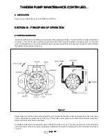
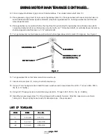
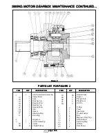
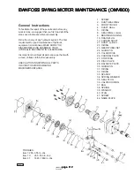
4. Using a 17 mm hexagon socket, remove the seven screws and washers (items 19 and 18).
5. Remove end cover (item 17) sideways.
6. Keeping fingers under gearwheel set (item 16) to prevent parts from falling out, remove gearwheel set and the two o-
rings (item 14).
7. Remove cardan shaft (item 10).
8. Remove distributor plate (item 15) and o-ring (also item 14).
9. Remove output shaft (item 9), then turn motor over.
10. Using a 0.15" screwdriver, remove dust seal ring (item 2).
11. Using a Torx spanner, type T30, remove the six screws (item 1).
12. Remove spigot flange (item 3).
13. Using a 0.08" screwdriver, remove o-ring (item 5) and bearing race (item 6).
14. Knock out the shaft seal (item 4) using a plastic hammer and 0.15" screwdriver.
15. Remove needle bearing (item 7).
16. Pull check valve (item 11) out with, for example, a ground down (shortened) 3.5 mm screw tap.
17. Clean all parts with low aromatic kerosine.
18. Check all parts carefully and replace if necessary.
19. Before reassembly, lubricate all parts with hydraulic oil and grease rubber parts with vaseline.
REASSEMBLY
REASSEMBLY
REASSEMBLY
REASSEMBLY
REASSEMBLY
1. Place motor housing in main holding tool with flange uppermost. Grease check valves (item 11) (check valves must
have new o-rings) and place them in the borings with a light blow from a plastic hammer.
2. Install needle bearing (item 7) and bearing race (item 6).
3. Knock shaft seal (item 4) into position in the spigot. Check that the shaft seal lies against cover recess.
4. Place dust seal ring (item 2) in spigot and knock it into position with plastic hammer and appropriate mandrel.
5. Grease o-ring (item 5) with vaseline and install it.
6. Install spigot flange (item 3). Turn so that holes line up.
7. Using a Torx spanner, type T30, install the six screws (item 1). Torque to 45 - 70 in. lbs. (0.5 - 0.8 daNm)
8. Install output shaft (item 9). For output shaft with splined shaft journal: Draw in India Ink a mark on shaft end, right
above one of the six commutating grooves facing the shaft journal. Lubricate shaft journals with hydraulic oil.
9. Install parallel key (item 8) in non-splined shaft, if used.
10. Grease o-ring (item 14) and put it in o-ring grooves of housing.
11. Install distributor plate (item 15). Turn distributor plate so that holes line up.
SWING MOTOR MAINTENANCE CONTINUED...
SWING MOTOR MAINTENANCE CONTINUED...
SWING MOTOR MAINTENANCE CONTINUED...
SWING MOTOR MAINTENANCE CONTINUED...
SWING MOTOR MAINTENANCE CONTINUED...

