


page 107
page 107
page 107
page 107
page 107
160B&C TM
800-00140
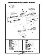
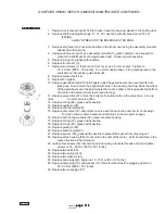
CARRIER SUB-ASSEMBLY
CARRIER SUB-ASSEMBLY
CARRIER SUB-ASSEMBLY
CARRIER SUB-ASSEMBLY
CARRIER SUB-ASSEMBLY
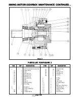
1. Apply grease to the inside of one planet gear (3F).
2. Line one half of planet gear (2F) with 16 needle rollers (3C).
3. Place one spacer (3D) inside planet gear (3F) so that it rests on top of the needle rollers (3C).
4. Line the remaining half of planet gear (3F) with 16 needle rollers (3C).
5. Stand carrier housing (3A) in an upright position.
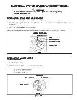
6. Insert a planet shaft (3E) into one of the planet shaft holes which also has a roll pin hole on carrier housing (3A).
The end of the planet shaft that does not have roll pin hole should be inserted into carrier housing first.
7. Place one thrust washer (3B) onto the end of planet shaft (3E) which has been inserted through the planet shaft
hole. Notice that the thrust washer has a tang on it: the tang should point straight down so as to fit within the
space in the raised inside edge of the planet shaft hole.
8. Following the thrust washer, place assembled planet gear (3F) onto planet shaft (3E).
9. Following the planet gear, place one more thrust washer (3B) onto planet shaft (3E). Now insert planet shaft
(3E) through the opposite planet shaft hole on carrier housing (3A).
10. Use an alignment punch or similar tool to align the roll pin holes on the carrier housing.
11. Drive roll pin (3G) down into the aligned roll pin holes.
12. Repeat steps 1 - 11 to assemble and install the two remaining planet gears.
13. At this point the carrier sub-assembly is complete.
HUB-SHAFT SUB-ASSEMBLY
HUB-SHAFT SUB-ASSEMBLY
HUB-SHAFT SUB-ASSEMBLY
HUB-SHAFT SUB-ASSEMBLY
HUB-SHAFT SUB-ASSEMBLY
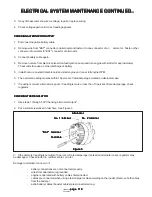
1. Oil output shaft (1A) and bearing cone (1D).
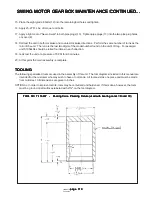
2. Using bearing cone pressing tool (T-116407), press bearing cone (1D) onto the end of output shaft (1A) that has
the retaining ring groove.
3. Stand hub (1G) on its small end. Using pressing tool (T-116412), press bearing cup (1E) down into hub (1G).
NOTE:
NOTE:
NOTE:
NOTE:
NOTE: Make sure that the cup sits square with the counterbore before pressing.
4. Turn hub (1G) over so that it rests on its large diameter end. Using bearing cup pressing tool (T-116412), press
bearing cup (1C) into the small end of hub (1G).
NOTE:
NOTE:
NOTE:
NOTE:
NOTE: Make sure that the cup sits square with the counterbore before pressing.
5. With hub (1G) still standing on its large end, place output shaft (1A) into hub (1G) so that the end of the shaft
with the retaining ring groove points down.
6. Oil output shaft (1A).
7. Using seal pressing tool (T-116402), press seal (1B) into the counterbore in the small end of hub (1G). The
closed face of the seal should be up.
8. Turn hub (1G) over so that its small end points down. Using bearing cone pressing tool (T-116407), press
bearing cone (1F) onto output shaft (1A). Rotate the hub while pressing the bearing. Stop pressing when the
hub starts to resist rotating.
9. Place spacer (1H) onto output shaft (1A) so that it rests on top of bearing cone (1F).
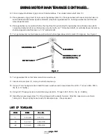
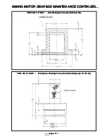
SWING MOTOR GEARBOX MAINTENANCE CONTINUED...
SWING MOTOR GEARBOX MAINTENANCE CONTINUED...
SWING MOTOR GEARBOX MAINTENANCE CONTINUED...
SWING MOTOR GEARBOX MAINTENANCE CONTINUED...
SWING MOTOR GEARBOX MAINTENANCE CONTINUED...


