


page 55
page 55
page 55
page 55
page 55
160B&C TM
800-00140
SECTION I - INTRODUCTION
SECTION I - INTRODUCTION
SECTION I - INTRODUCTION
SECTION I - INTRODUCTION
SECTION I - INTRODUCTION
A. PURPOSE OF MANUAL
A. PURPOSE OF MANUAL
A. PURPOSE OF MANUAL
A. PURPOSE OF MANUAL
A. PURPOSE OF MANUAL
This manual describes basic operational characteristics and provides service and overhaul information for the
transmission pump package. The information contained herein pertains to the latest design series.
B. GENERAL INFORMATION
B. GENERAL INFORMATION
B. GENERAL INFORMATION
B. GENERAL INFORMATION
B. GENERAL INFORMATION
1. Related Publications - Service parts information and installation dimensions are not contained in this manual. See
Parts Manual.
2. Model Codes - Variations within each basic model series are covered in the model code.
SECTION II - DESCRIPTION
SECTION II - DESCRIPTION
SECTION II - DESCRIPTION
SECTION II - DESCRIPTION
SECTION II - DESCRIPTION
A. GENERAL
A. GENERAL
A. GENERAL
A. GENERAL
A. GENERAL
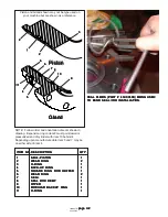
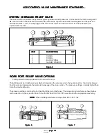
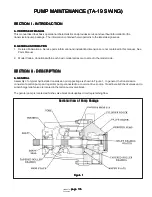
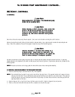
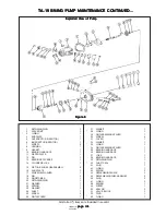
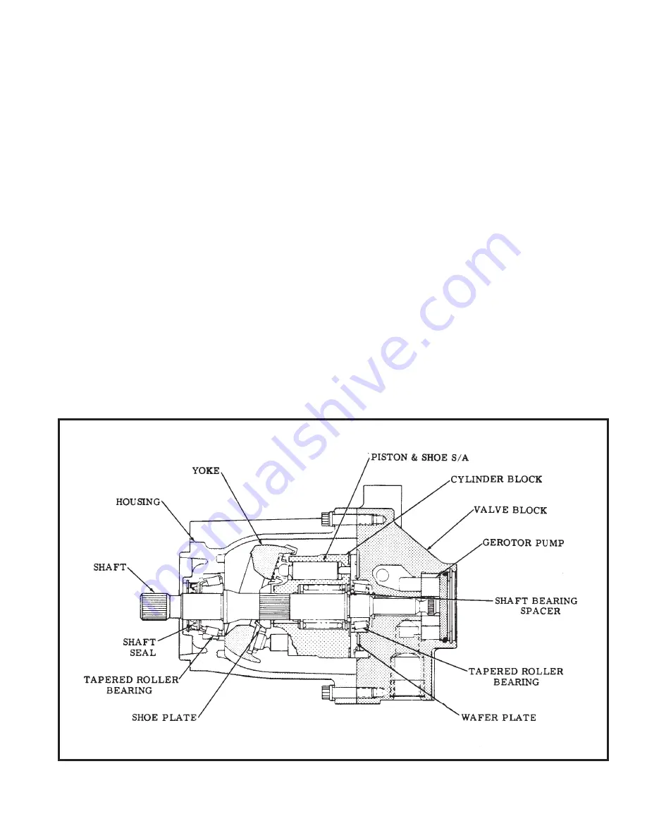
Assembly of a typical hydrostatic transmission pump package is shown in Figure 1. In general, the transmission
consists of a piston pump and a gerotor pump connected to a common drive source. Crossline relief/check valves and a
supercharge relief valve are located in the piston pump valve block.
The gerotor pump is located within the valve block and supplies circuit replenishing flow.
PUMP MAINTENANCE (TA-19 SWING)
PUMP MAINTENANCE (TA-19 SWING)
PUMP MAINTENANCE (TA-19 SWING)
PUMP MAINTENANCE (TA-19 SWING)
PUMP MAINTENANCE (TA-19 SWING)
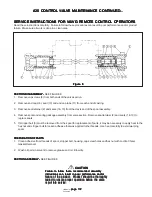
Sectional View of Pump Package
Sectional View of Pump Package
Sectional View of Pump Package
Sectional View of Pump Package
Sectional View of Pump Package
Figure 1
Figure 1
Figure 1
Figure 1
Figure 1


