page 56
page 56
page 56
page 56
page 56
160B&C TM
800-00140
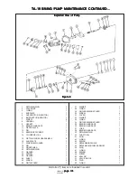
TA-19 SWING PUMP MAINTENANCE CONTINUED...
TA-19 SWING PUMP MAINTENANCE CONTINUED...
TA-19 SWING PUMP MAINTENANCE CONTINUED...
TA-19 SWING PUMP MAINTENANCE CONTINUED...
TA-19 SWING PUMP MAINTENANCE CONTINUED...
B. APPLICATION
B. APPLICATION
B. APPLICATION
B. APPLICATION
B. APPLICATION
Pump rating in USGPM as shown in the model coding are at 1800 RPM. For ratings at others speeds, methods of
installation and other application information, consult the factory.
SECTION III - PRINCIPLES OF OPERATION
SECTION III - PRINCIPLES OF OPERATION
SECTION III - PRINCIPLES OF OPERATION
SECTION III - PRINCIPLES OF OPERATION
SECTION III - PRINCIPLES OF OPERATION
A. PISTON PUMP
A. PISTON PUMP
A. PISTON PUMP
A. PISTON PUMP
A. PISTON PUMP
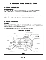
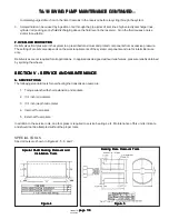
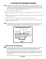
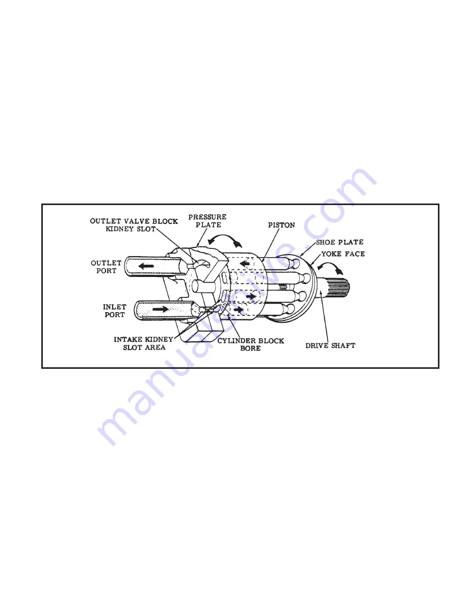
The drive shaft causes the cylinder block, pistons and shoe plate to rotate within the pump. See Figure 2. The angle of
the yoke face imparts a reciprocating motion to each piston within the cylinder block. Inlet and outlet ports connect to a
kidney slotted wafer plate. As the pistons move out of the cylinder block a vacuum is created and fluid is forced into the
void by replenishing pressure. The fluid moves with the cylinder block past the intake kidney slot to the outlet (pressure)
kidney slot. The motion of the piston reverses and fluid is pushed out of the cylinder block into the outlet port.
B. GEROTOR PUMP
B. GEROTOR PUMP
B. GEROTOR PUMP
B. GEROTOR PUMP
B. GEROTOR PUMP
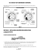
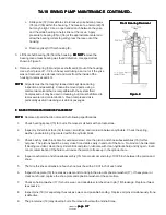
A gerotor pump is composed of three basic parts, an inner rotor and outer rotor and a housing. Refer to Figure 3. The
inner and outer rotor are machined to very close tolerances to limit internal leakage.
The inner rotor is driven by the main pump shaft and carries the outer rotor around in mesh. As the rotors turn, the inner
rotor lobe tips ride against the curvature of the outer rotor forming individual pumping chambers and sealing them from
each other. The pumping chambers form at the top right of the center lines shown in Figure 3. As each chambers
volume increases, pressure within each chamber lowers causing a vacuum condition to exist. Atmospheric pressure
pushes system fluid through the inlet into the chambers to equalize pressure. This action continues while the chambers
move past the inlet kidney slot, (shown by dotted lines in Figure 3).
When the center of a chamber moves past the bottom centerline, shown in Figure 3, chamber volume starts to decrease
and fluid is pushed into the outlet kidney slot.
The action of the inner and outer rotor is such that a given amount of fluid is moved from the inlet port to the outlet port
each revolution. The output of the pump, except for leakage losses, is independent of outlet pressure.
Figure 2
Figure 2
Figure 2
Figure 2
Figure 2

