page 65
page 65
page 65
page 65
page 65
160B&C TM
800-00140
C. INSPECTION REPAIR AND REPLACEMENT
C. INSPECTION REPAIR AND REPLACEMENT
C. INSPECTION REPAIR AND REPLACEMENT
C. INSPECTION REPAIR AND REPLACEMENT
C. INSPECTION REPAIR AND REPLACEMENT
NOTE:
NOTE:
NOTE:
NOTE:
NOTE: Replace all parts that do not meet the following specifications.
NOTE:
NOTE:
NOTE:
NOTE:
NOTE: All parts must be thoroughly cleaned and kept clean during inspection and assembly. The close tolerance of the
parts makes this requirement very important. Clean all removed parts using a commercial solvent that is
compatible with the system fluid. Compressed air may be used in cleaning, but it must be filtered to remove
water and contamination. Clean compressed air is particularly useful in cleaning the relief valve spool and valve
block passages.
1. Check all components for excessive wear and erosion.
2. Check each lobe of the inner and outer rotors for evidence of seizure.
3. Inspect the sides and outer edge of the rotors for evidence of pickup or wear. Install the outer rotor into the valve
block and check for bind and/or excessive wear.
NOTE:
NOTE:
NOTE:
NOTE:
NOTE: If failure of the gerotor gear set has occurred, check the valve block and the cover for defects. Replace all parts
that show deep cuts or scratches.
4. Place cleaned parts on a piece of Kraft paper and cover them to prevent dirt contamination. These parts will be used
during final assembly of the pump.
D. DISASSEMBLY OF PISTON PUMP ROTATING GROUP AND VALVE BLOCK
D. DISASSEMBLY OF PISTON PUMP ROTATING GROUP AND VALVE BLOCK
D. DISASSEMBLY OF PISTON PUMP ROTATING GROUP AND VALVE BLOCK
D. DISASSEMBLY OF PISTON PUMP ROTATING GROUP AND VALVE BLOCK
D. DISASSEMBLY OF PISTON PUMP ROTATING GROUP AND VALVE BLOCK
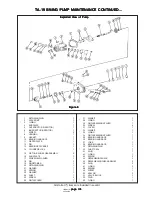
1. Remove six screws (7) from housing (8). Separate housing (8) and valve block (51).
2. Remove gasket (9) then slide tapered roller bearing (10) from the end of shaft (24).
3. Remove wafer plate (11) from valve block (51) then remove pin (12) from valve block.
4. Slide bearing spacer (13) off shaft (24).
5. Remove rotating group parts (14 through 23) as a unit. Hold the shoe plate (16), piston and shoe subassemblies
(15), and cylinder block (14) to prevent separation of the rotating group during removal.
NOTE:
NOTE:
NOTE:
NOTE:
NOTE: The rotating group consists of a cylinder block (14), nine piston and shoe subassemblies (15), a shoe plate (16),
a spherical washer (17), three pins (18), a pin retainer (19), retaining ring (20), washer (21) spring (22) and flat
washer (23).
CAUTION
CAUTION
CAUTION
CAUTION
CAUTION
In the following step, the spring located within the
In the following step, the spring located within the
In the following step, the spring located within the
In the following step, the spring located within the
In the following step, the spring located within the
cylinder block is under a high tension and can cause
cylinder block is under a high tension and can cause
cylinder block is under a high tension and can cause
cylinder block is under a high tension and can cause
cylinder block is under a high tension and can cause
bodily harm if the retaining ring (20) is removed with out
bodily harm if the retaining ring (20) is removed with out
bodily harm if the retaining ring (20) is removed with out
bodily harm if the retaining ring (20) is removed with out
bodily harm if the retaining ring (20) is removed with out
adequate caution.
adequate caution.
adequate caution.
adequate caution.
adequate caution.
6. Remove parts (20 through 23) from cylinder block (14).
7. Disassemble valve block (51) as follows:
NOTE:
NOTE:
NOTE:
NOTE:
NOTE: Mark each valve to permit reassembly into the same bore opening. The check valves develop a wear pattern
within the valve block and may leak if the valves are interchanged.
TA-19 SWING PUMP MAINTENANCE CONTINUED...
TA-19 SWING PUMP MAINTENANCE CONTINUED...
TA-19 SWING PUMP MAINTENANCE CONTINUED...
TA-19 SWING PUMP MAINTENANCE CONTINUED...
TA-19 SWING PUMP MAINTENANCE CONTINUED...

