


page 70
page 70
page 70
page 70
page 70
160B&C TM
800-00140
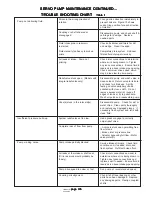
TA-19 SWING PUMP MAINTENANCE CONTINUED...
TA-19 SWING PUMP MAINTENANCE CONTINUED...
TA-19 SWING PUMP MAINTENANCE CONTINUED...
TA-19 SWING PUMP MAINTENANCE CONTINUED...
TA-19 SWING PUMP MAINTENANCE CONTINUED...
3.
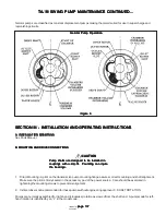
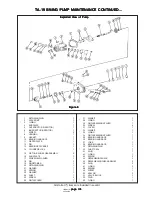
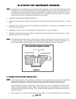
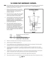
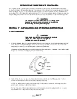
Orient the yoke pintle properly and install yoke (37) into housing (8). Assemble the yoke bearings, races, and
spacers as follows:
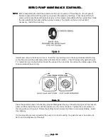
a. Assemble pintle bearings (35) and (36) on each end of the yoke and insert bearing races (35) and (36). See
Figure 8.
b. Install bearing spacer (34) at the short pintle end.
c. Install o-ring (33) against spacer (34) into the groove, then install a 0.010 inch shim (32) under pintle cover
screws (30) and torque to 175-185 lb. ft. (237-251 N.m). Early designs used a screw and washer
arrangement. These should be torqued to 115-125 lb. ft. (156-169 N.m).
d. Set housing (8) on it's side so the long pintle is up. Install bearing spacer (29) fully in against the bearing
race. Install the pintle cover (26), (without shims and o-ring), then thread four pintle screws (25) through the
cover into the housing. Cross torque the screws to 2 lb. inches while moving the yoke back and forth to
align the bearings and races, (keep cover as square to pintle boss as possible). Continue to cross torque
the cover screws until the yoke has a constant drag and the attaching screws are set to 2 lb. in. torque.
Remove the cover being careful not to disturb the yoke bearings and spacer. Measure the height of the
spacer with respect to the housing pintle face in two places (180
o
apart). Use a depth micrometer to
perform this measurement. Average the readings to obtain a nominal value. A 0.007-0.009 inch preload is
required on the pintle bearing.
Calculate the necessary shims to provide this preload as follows: Assume the depth readings were 0.029
and 0.027 inch. Add the two figures together and divide by two (2) to obtain the average. In this case the
calculated average is 0.028 inch. Subtract the nominal preload of 0.008 inch from the calculated average to
obtain the required shim thickness.
NOTE:
NOTE:
NOTE:
NOTE:
NOTE: If the calculated shim thickness is greater than 0.020, another shim must be added to the opposite side of the
yoke to reduce the total shim thickness to less than 0.020 inch. Shim thickness at either pintle must not
exceed 0.020 inch. This is necessary to provide proper o-ring compression and prevent pintle seal leakage.
e. Install o-ring (28) and correct shims (27). Slide cover (26) over yoke pintle and flush against the shims.
Insert screws (25) through pintle cover (26) and thread into pintle face. Cross torque screws to 175-185 lb.
ft., (237-251 N.m). Early designs used a screw and washer arrangement. These should be torqued to 115-
125 lb. ft., (156-169 N.m)
NOTE:
NOTE:
NOTE:
NOTE:
NOTE: The yoke (37) will be stiff but should be loose enough to be moved by hand, approximately 20 lb. in. torque. The
tightness/drag indicates the bearings are preloaded. If the yoke cannot be moved by hand, the preload is too
great. Repeat the preload adjustment until correct.
4.
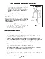
Install shaft (24) into front shaft bearing (38) as follows:
Use a short piece of 1-1/2 inch heavy wall tubing (approximately 6 inches long) over the drive spline of the shaft.
The tubing must be long enough to go through the shaft seal end of the pump and make contact with the inner
race of the front bearing. Press the shaft through the bearing with an arbor press until the bearing bottoms
against the shoulder of the shaft. See Figure 11.
5.
Remove the short piece of tubing and turn shaft bearing (38) in it's race with the end of the shaft. The bearing
rollers must turn free and smooth.
6.
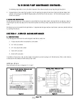
Tape the spline end of drive shaft (24) with plastic tape to prevent cutting new shaft seal (40). Start taping the
shaft close to the housing and work toward the end of the shaft. Install a new shaft seal (40) (garter spring
inward) in position over the shaft and press evenly into the housing. Use shaft seal driver shown in Figure 7.
The seal must be positioned just below the retaining ring groove. If the seal is pressed too deep into the housing
bore, contact with the tapered roller bearing can damage the seal. DO NOT
DO NOT
DO NOT
DO NOT
DO NOT press the seal more than 0.020
inch past the retaining ring groove. Install retaining ring (39) into the housing. Use internal Truarc pliers to
install retaining ring.


