page 72
page 72
page 72
page 72
page 72
160B&C TM
800-00140
subassemblies (15) over the spherical washer into the cylinder block S/A. Wobble the shoe plate to make sure
that each piston is free within it's bore in the cylinder block.
18.
Set housing (8) on it's side and hold the shaft end so drive shaft (24) is horizontal. Slide the rotating group into
the housing. Rotate drive shaft (24) if necessary, to match the shaft splines to cylinder block (14) and spherical
washer (17).
19.
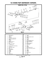
Install bearing spacer (13) with chamfer toward the shoulder of drive shaft (24).
20.
Install tapered roller bearing (10) over the shaft and against the spacer. The small diameter of the tapered roller
bearing must face toward valve block (51).
21.
Install two (2) housing alignment pins (50) and place a new gasket (9) over them. Cover the unit and set aside
for final assembly.
I. FINAL ASSEMBLY OF PISTON PUMP, VALVE BLOCK, AND GEROTOR PUMP
I. FINAL ASSEMBLY OF PISTON PUMP, VALVE BLOCK, AND GEROTOR PUMP
I. FINAL ASSEMBLY OF PISTON PUMP, VALVE BLOCK, AND GEROTOR PUMP
I. FINAL ASSEMBLY OF PISTON PUMP, VALVE BLOCK, AND GEROTOR PUMP
I. FINAL ASSEMBLY OF PISTON PUMP, VALVE BLOCK, AND GEROTOR PUMP
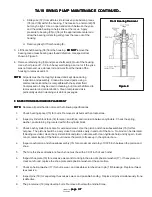
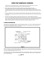
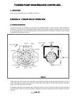
1. Assemble wafer plate locating pin (12) into valve block (51). Refer to Figure 8.
2. Assemble wafer plate (11) over the bearing race and locating pin (12) with bronze surface away from valve block (51).
Make sure wafer plate is flat against valve block (51).
3. Place valve block (51) on it's side. See Figure 8 for position required.
4. Assemble housing (8) against valve block (51) with six screws (7), cross torque the screws to 23-26 lb. ft. (31-35
N.m).
5. Assemble the gerotor pump as follows:
a. Turn the piston pump to gain access to the valve block opening (shaft end downward).
b. Lubricate the inner and outer rotors with system fluid, then install inner rotor (6) over the shaft spline. Install
outer rotor (5) in mesh with the inner rotor within the valve block cavity.
c. Install cover (4) into valve block (51) with o-ring groove toward the outside of the unit.
d. Install the o-ring (3) into place.
e. Install spacer (2) and retaining ring (1). Make sure the rolled edges of retaining ring (1) face inward (sharp
edges out).
6. Assemble a new o-ring (53) over plug (52) and thread in place. Torque to 90-100 lb. ft. (122-135 N.m).
TA-19 SWING PUMP MAINTENANCE CONTINUED...
TA-19 SWING PUMP MAINTENANCE CONTINUED...
TA-19 SWING PUMP MAINTENANCE CONTINUED...
TA-19 SWING PUMP MAINTENANCE CONTINUED...
TA-19 SWING PUMP MAINTENANCE CONTINUED...

