page 73
page 73
page 73
page 73
page 73
160B&C TM
800-00140
PUMP MAINTENANCE (SERVO)
PUMP MAINTENANCE (SERVO)
PUMP MAINTENANCE (SERVO)
PUMP MAINTENANCE (SERVO)
PUMP MAINTENANCE (SERVO)
Typical Servo Pump
Typical Servo Pump
Typical Servo Pump
Typical Servo Pump
Typical Servo Pump
Figure 1
Figure 1
Figure 1
Figure 1
Figure 1
SECTION I - INTRODUCTION
SECTION I - INTRODUCTION
SECTION I - INTRODUCTION
SECTION I - INTRODUCTION
SECTION I - INTRODUCTION
A. PURPOSE OF MANUAL
A. PURPOSE OF MANUAL
A. PURPOSE OF MANUAL
A. PURPOSE OF MANUAL
A. PURPOSE OF MANUAL
This manual has been prepared to assist the users of balanced vane type hydraulic single pumps in properly installing,
maintaining, and repairing their units. In the sections which follow, the single pumps are described in detail, their theory of
operation is discussed and instructions are given for their proper installation, maintenance, and overhaul.
SECTION II - DESCRIPTION
SECTION II - DESCRIPTION
SECTION II - DESCRIPTION
SECTION II - DESCRIPTION
SECTION II - DESCRIPTION
A. GENERAL
A. GENERAL
A. GENERAL
A. GENERAL
A. GENERAL
Pumps in this series are used to develop hydraulic fluid flow for the operation of Mobile and Industrial equipment. The positive
displacement pumping cartridges are the rotary vane type with shaft side loads hydraulically balanced. The flow rate depends
on the pump size and the speed at which it is driven.
All units are designed so that the direction of rotation, pumping capacity, and port positions can be readily changed to suit
particular applications.
B. ASSEMBLY AND CONSTRUCTION
B. ASSEMBLY AND CONSTRUCTION
B. ASSEMBLY AND CONSTRUCTION
B. ASSEMBLY AND CONSTRUCTION
B. ASSEMBLY AND CONSTRUCTION
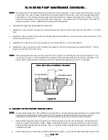
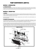
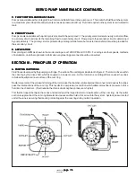
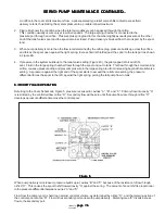
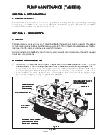
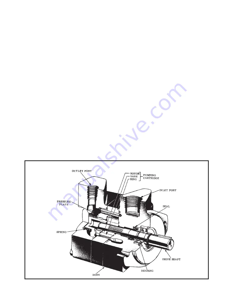
The pump illustrated in the cut-a-way in Figure 1 on next page is representative of all single pumps in this series. The unit
consists principally of a ported body, a ported cover and a pumping cartridge. Components of the pumping cartridge are an
elliptical cam ring, a slotted rotor splined to fit the drive shaft and twelve vanes fitted to the rotor slots.
The pumping cartridge cam ring is sandwiched between the body and cover. A ball bearing and bushing located in the body
and pressure plate respectively support each end of the drive shaft and center the rotor within the cam ring. As the drive shaft
is driven by the prime mover, the rotor and vanes generate flow by carrying fluid around the elliptical cam ring contour. Fluid
enters the cartridge through the inlet port in the body and is discharged through the pressure plate into the outlet port of the
cover.

