page 76
page 76
page 76
page 76
page 76
160B&C TM
800-00140
An orifice in the cover limits maximum flow. A pilot-operated type relief valve shifts to divert excess fluid
delivery to tank, thus limiting the system pressure to a predetermined maximum.
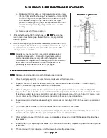
2. Figure 4A shows the condition when the total pump delivery can be passed through the orifice.
This condition usually occurs only at low drive speeds. The large spring chamber is connected to the
pressure port through an orifice. Pressure plus spring load in this chamber slightly exceeds pressure at the other
end of the relief valve spool and the spool remains closed. Pump delivery is blocked from the tank port by the spool
land.
3. When pump delivery is more than the flow rate determined by the orifice plug, pressure builds up acrossthe orifice
and forces the spool open against the light spring. Excess fluid is throttled past the spool to the tank port as shown
in Figure 4B.
4. If pressure in the system builds up to the relief valve setting (Figure 4C), the pilot poppet is forced off it’s
seat. Fluid in the large spring chamber flows through the spool and out to tank. This flow through the small sensing
orifice, causes a pressure drop and prevents pressure in the large spring area from increasing beyond the relief valve
setting. As pressure against the right end of the spool starts to exceed the relief valve setting, the pressure
differential forces the spool to the left, against the light spring, porting the full pump flow to tank.
E. PRIORITY VALVE OPERATION
E. PRIORITY VALVE OPERATION
E. PRIORITY VALVE OPERATION
E. PRIORITY VALVE OPERATION
E. PRIORITY VALVE OPERATION
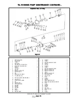
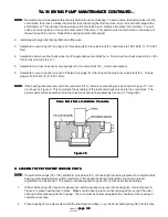
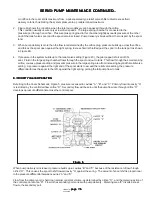
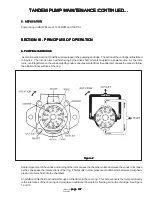
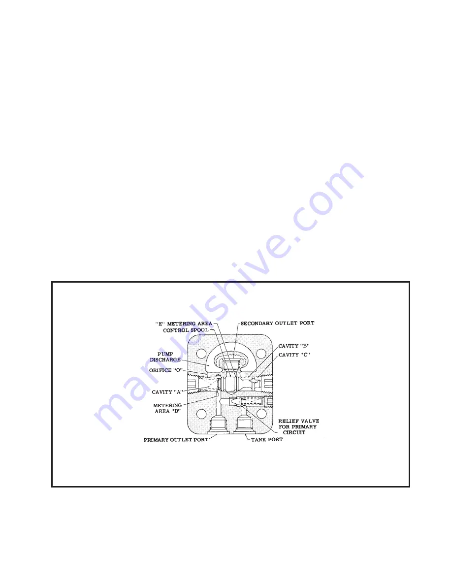
Referring to the Cover Schematic, Figure 5, pressure is sensed in cavities “A”, “B”, and “C”. Primary flow into cavity “A”
is restricted by the controlled flow orifice “O”. Secondary flow will be zero until the pump flow rate through orifice “O”
develops a pressure differential across the control spool.
Figure 5
Figure 5
Figure 5
Figure 5
Figure 5
When pump delivery is increased, pressure builds up in cavities “B” and “C” because of the resistance to flow through
orifice “O”. This causes the spool to shift toward cavity “A” against the spring. The amount of spool shift is proportional
to the pressure differential between cavities “A” and “C”.
Flow from the primary port is held to an almost constant volume, as determined by orifice “O”, and the metering action of
the control spool at area “D”. Flow to the secondary port varies with pump delivery. Metering area “E” diverts excess
flow to the secondary port.
SERVO PUMP MAINTENANCE CONTINUED...
SERVO PUMP MAINTENANCE CONTINUED...
SERVO PUMP MAINTENANCE CONTINUED...
SERVO PUMP MAINTENANCE CONTINUED...
SERVO PUMP MAINTENANCE CONTINUED...


