page 88
page 88
page 88
page 88
page 88
160B&C TM
800-00140
Fluid is trapped between the vanes and carried past a sealing and to the outlet section of the ring. As the outlet
section is approached, the chamber volume decreases and fluid is forced out into the system. System pressure is
fed under the vanes, assuring their sealing contact against the ring during normal operation.
B. VANE PRESSURE FEED
B. VANE PRESSURE FEED
B. VANE PRESSURE FEED
B. VANE PRESSURE FEED
B. VANE PRESSURE FEED
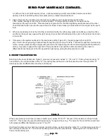
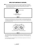
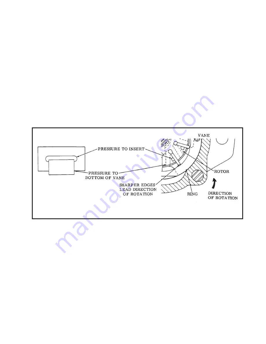
The intra-vane design provides a means of controlling the outward thrust of the vane against the ring and maintains
tip loads within reasonable limits. In the intra-vane cartridge, full system pressure is continuously applied only to
the area between the vane and insert. This area is small and thrust is correspondingly light. During vane travel through
pressure areas, full system pressure is applied against the bottom area of the outer vane. The valving of pressure
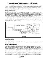
to and from the bottom area of the vane is through holes drilled in the rotor, as shown in
Figure 3. This selective application of pressure maintains the vane in substantially constant radial hydraulic balance
in all positions.
Vane tip wear is compensated for automatically. As the vane wears, pressure moves the vane farther out in the rotor
slot holding the vane tip against the cam ring.
Figure 3
Figure 3
Figure 3
Figure 3
Figure 3
C. HYDRAULIC BALANCE
C. HYDRAULIC BALANCE
C. HYDRAULIC BALANCE
C. HYDRAULIC BALANCE
C. HYDRAULIC BALANCE
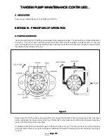
The pump ring is shaped so the two pumping chambers are formed 180 degrees apart (Figure 2). Thus, opposing
hydraulic forces which develop side loads on the shaft cancel out.
D. FLEX SIDE PLATE OPERATION
D. FLEX SIDE PLATE OPERATION
D. FLEX SIDE PLATE OPERATION
D. FLEX SIDE PLATE OPERATION
D. FLEX SIDE PLATE OPERATION
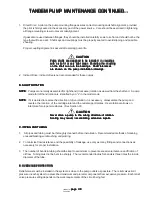
The flex side plates for both inlet and outlet are symmetrical. Pressure is fed behind each side plate into two
kidney shaped cavities, which are sealed by special seal pack subassemblies. The two flex side plates and their
associated kidney shaped cavities function in the following manner. As pressure builds up in the outlet, pressure
also builds up in the cavities. The pressure in the cavities hold the flex side plates in hydrostatic balance against
the rotor and provide optimum running clearances for minimum internal leakage and minimum friction. (See Figure
4 on next page)
The flex side plates also provide passages for feeding under vane pressure to the space between the vane and insert.
The bronze faces of the flex side plates ride next to the rotor and provide excellent wear and cold start characteristics.
TANDEM PUMP MAINTENANCE CONTINUED...
TANDEM PUMP MAINTENANCE CONTINUED...
TANDEM PUMP MAINTENANCE CONTINUED...
TANDEM PUMP MAINTENANCE CONTINUED...
TANDEM PUMP MAINTENANCE CONTINUED...

