


page 97
page 97
page 97
page 97
page 97
160B&C TM
800-00140
CAUTION
CAUTION
CAUTION
CAUTION
CAUTION
Replacement ring width must be identical to the
Replacement ring width must be identical to the
Replacement ring width must be identical to the
Replacement ring width must be identical to the
Replacement ring width must be identical to the
ring being replaced or reduced life and/or output
ring being replaced or reduced life and/or output
ring being replaced or reduced life and/or output
ring being replaced or reduced life and/or output
ring being replaced or reduced life and/or output
flow will result. The minimum ring to rotor clearance
flow will result. The minimum ring to rotor clearance
flow will result. The minimum ring to rotor clearance
flow will result. The minimum ring to rotor clearance
flow will result. The minimum ring to rotor clearance
limits are .0015 on Shaft End and .0012 on Cover End.
limits are .0015 on Shaft End and .0012 on Cover End.
limits are .0015 on Shaft End and .0012 on Cover End.
limits are .0015 on Shaft End and .0012 on Cover End.
limits are .0015 on Shaft End and .0012 on Cover End.
NOTE:
NOTE:
NOTE:
NOTE:
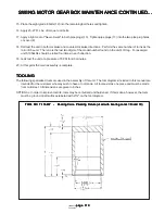
NOTE: All cartridge kit parts must be free of burrs. Stone the mating surfaces of each part with an oiled Arkansas
stone prior to assembly.
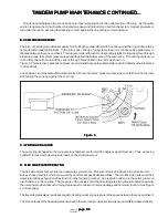
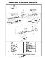
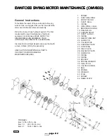
4. Vane to rotor wear can be checked by inserting the vane in the rotor slot and checking for excessive play.
Replace rotor (28) and vanes (29) if wear is evident.
5. Rotate bearing (12) while applying pressure to check for wear, looseness and pitted or cracked races.
6. Inspect the seal and bushing mating surfaces on shaft (9) for scoring or wear. Replace the shaft if wear
exceeds 0.005 diametrical change, or if marks cannot be removed by light polishing If wear is found in the
bushing area, a new bushing will be required.
D. ASSEMBLY
D. ASSEMBLY
D. ASSEMBLY
D. ASSEMBLY
D. ASSEMBLY
NOTE:
NOTE:
NOTE:
NOTE:
NOTE: Coat all parts except seals and back-up rings with clean hydraulic fluid to facilitate assembly and provide
initial lubrication. Use small amounts of petroleum jelly to hold the o-rings in place during assembly.
IMPORTANT:
IMPORTANT:
IMPORTANT:
IMPORTANT:
IMPORTANT: During handling and shipping of precision machined cartridge parts, it is possible to raise burrs
on the sharp edges. All sharp edges of new cartridge kit should be stoned prior to installation.
NOTE:
NOTE:
NOTE:
NOTE:
NOTE: To reverse direction of a new cartridge kit, simply reverse location of the inlet and outlet support plates,
and realign the cartridge with a “V” block or fixture made from two pieces of hardwood nailed together.
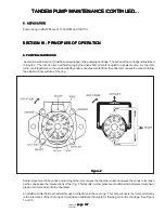
1. Cartridge: The direction of rotation is viewed from the shaft end; right hand rotation is clockwise; left hand
counterclockwise.
NOTE:
NOTE:
NOTE:
NOTE:
NOTE: Assemble shaft end cartridge (7) in the direction of rotation noted by model code. Assemble cover end
cartridge (4) in reverse of the shaft end cartridge.
NOTE:
NOTE:
NOTE:
NOTE:
NOTE: If locating pins (30) were removed from inlet support plate (21), install new pins with locking flutes located
within the inlet support plate. Drive the new pins into the support plate, with a soft tip hammer.
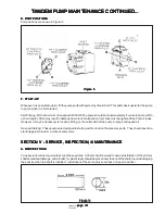
a. Place the inlet and outlet support plates on a flat surface. Install seal pack subassemblies (22 and
25) into cavities with seal retainer surface up. (O-rings facing downward into the cavities).
b. Place flex side plates (23 and 26) over each of the support plates with bronze wear surface facing
up. Align scribe marks to make sure the correct flex side plate is used with the correct support plate.
(Bronze wear surface must face rotor when assembled).
NOTE:
NOTE:
NOTE:
NOTE:
NOTE: Flex side plates develop a wear pattern with the rotor and vanes and should not be interchanged.
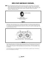
c. For right hand rotation units, set the rotor on a flat wooden board with the arrow pointing right.
(For left hand rotation, the arrow should point left). Assemble the vanes and inserts into the
rotor in reverse order. Make sure the sharp chamfer edge of each vane leads in the direction of
rotation. All vanes must move freely in the rotor slots with no evidence of bind.
d. Assemble the ring (27) over rotor (28) and vanes (29) with arrow pointing in the same direction as
the rotor. Lubricate the top surface of the rotor and vanes liberally with system fluid.
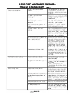
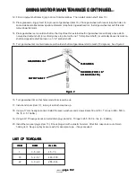
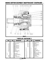
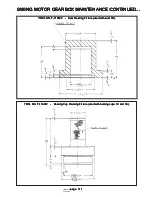
TANDEM PUMP MAINTENANCE CONTINUED...
TANDEM PUMP MAINTENANCE CONTINUED...
TANDEM PUMP MAINTENANCE CONTINUED...
TANDEM PUMP MAINTENANCE CONTINUED...
TANDEM PUMP MAINTENANCE CONTINUED...


