page 98
page 98
page 98
page 98
page 98
160B&C TM
800-00140
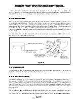
e. Locate the scribe mark on ring (27), outlet support plate (24), and flex side plate (26). Hold the
outlet support plate and flex side plate together and assemble over the ring and rotor with the scribe
marks in-line.
f.
Hold the cartridge together to prevent movement and turn the assembly over so the outlet support
plate rests on a flat surface, and the wooden board is up. Remove the wooden board.
g. Lubricate the exposed surface of the rotor and vanes with system fluid. Locate the scribe mark on
inlet support plate (21) and flex side plate (23). Hold the inlet support plate and flex side plate together
and assemble over the exposed ring, rotor and vane. Make sure the scribe marks are in line.
NOTE:
NOTE:
NOTE:
NOTE:
NOTE: The cast-in arrows located next to the socket head screws, indicate cartridge direction of rotation.
h. Thread two socket head screws (20) into the cartridge until snug (hand tight).
NOTE:
NOTE:
NOTE:
NOTE:
NOTE: The O.D. of all component parts of the cartridge kit must be in-line with each other or the cartridge
will bind during assembly. Align the cartridge as follows:
i. Build a “V” block from hardwood or if a metal “V” block is available, use that. Place the cartridge
into the “V” block on its side. Loosen socket head screws (20) enough to allow each section of
the cartridge to come into alignment within the “V” block. Torque tighten socket head screws
(20) as noted in Table 2. Recheck alignment after tightening.
Cover End -
25
Shaft End -
35
j.
Check rotor (28) for bind by inserting the index finger through the shaft ope
t ope
t ope
t ope
t opening of inlet support
plate (21). Hold the cartridge kit in a horizontal shaft position and lift the rotor with the finger.
The rotor should move freely back and forth within the cartridge. If the rotor binds, open the kit,
clean and stone all possible areas of bind, then reassemble using the aforementioned procedure. The
rotor MUST move freely within the cartridge when assembled.
NOTE:
NOTE:
NOTE:
NOTE:
NOTE: Repeat step D1 for the other cartridge kit.
2. Basic Pump: Clamp outlet body (15) in a vise or place on 2 x 4 wood blocks to facilitate assembly.
a. Lubricate shaft seal (14) with petroleum jelly and place in position within outlet body (15), garter
spring up.
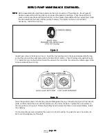
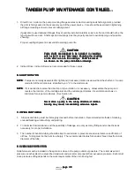
b. Use the seal installation tool shown in Figure 6 to prevent damage to the seal. Press seal (14) into
the body until it bottoms out against the shoulder.
NOTE:
NOTE:
NOTE:
NOTE:
NOTE: If shaft bearing (12) was defective, install a new bearing as follows:
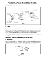
c. Press shaft (9) into the new bearing with an arbor press while supporting the bearing inner race. Refer
to Figure 7 for correct location of bearing on the shaft. Install a small retaining ring (11) behind
the bearing on the shaft.
Table 2
Table 2
Table 2
Table 2
Table 2
CARTRIDGE SIZE
CARTRIDGE SIZE
CARTRIDGE SIZE
CARTRIDGE SIZE
CARTRIDGE SIZE
CARTRIDGE SCREW TORQUE
CARTRIDGE SCREW TORQUE
CARTRIDGE SCREW TORQUE
CARTRIDGE SCREW TORQUE
CARTRIDGE SCREW TORQUE
50 lb. in.
100 lb. in.
TANDEM PUMP MAINTENANCE CONTINUED...
TANDEM PUMP MAINTENANCE CONTINUED...
TANDEM PUMP MAINTENANCE CONTINUED...
TANDEM PUMP MAINTENANCE CONTINUED...
TANDEM PUMP MAINTENANCE CONTINUED...

