page 78
page 78
page 78
page 78
page 78
275B SER
800-00152
ELECTRICAL MOTOR COUPLING MAINTENANCE
ELECTRICAL MOTOR COUPLING MAINTENANCE
ELECTRICAL MOTOR COUPLING MAINTENANCE
ELECTRICAL MOTOR COUPLING MAINTENANCE
ELECTRICAL MOTOR COUPLING MAINTENANCE
CONTINUED...
CONTINUED...
CONTINUED...
CONTINUED...
CONTINUED...
INSTALLATION OF TAPERED GRID
INSTALLATION OF TAPERED GRID
INSTALLATION OF TAPERED GRID
INSTALLATION OF TAPERED GRID
INSTALLATION OF TAPERED GRID
COUPLINGS
COUPLINGS
COUPLINGS
COUPLINGS
COUPLINGS
1. MOUNT SEALS AND HUBS
1. MOUNT SEALS AND HUBS
1. MOUNT SEALS AND HUBS
1. MOUNT SEALS AND HUBS
1. MOUNT SEALS AND HUBS
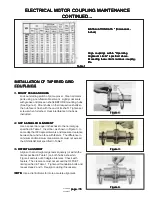
Lock out starting switch of prime mover. Clean all metal
parts using a non-flammable solvent. Lightly coat seals
with grease and place on shafts BEFORE mounting hubs
(See Figure 2). Mount hubs on their respective shafts so
the hub face is flush with the end of its shaft. Tighten set
screws when furnished. Heat interference fit hubs as
instructed.
2. GAP & ANGULAR ALIGNMENT
2. GAP & ANGULAR ALIGNMENT
2. GAP & ANGULAR ALIGNMENT
2. GAP & ANGULAR ALIGNMENT
2. GAP & ANGULAR ALIGNMENT
Use a spacer bar equal in thickness to the normal gap
specified in Table 1. Insert bar, as shown in Figure 3, to
same depth at 90 degree intervals and measure clearance
between bar and hub face with feelers. The difference in
minimum and maximum measurements must not exceed
the ANGULAR limit specified in Table 1.
3. OFFSET ALIGNMENT
3. OFFSET ALIGNMENT
3. OFFSET ALIGNMENT
3. OFFSET ALIGNMENT
3. OFFSET ALIGNMENT
Align so that a straight edge rests squarely (or within the
limits specified in Table 1) on both hubs a shown in
Figure 4 and also at 90 degree intervals. Check with
feelers. The clearance must not exceed the OFFSET
limit specified in Table 1. Tighten all foundation bolts and
repeat steps 2 and 3. Realign coupling if necessary.
NOTE:
NOTE:
NOTE:
NOTE:
NOTE: Use a dial indicator for more accurate alignment.
Figure 2
Figure 2
Figure 2
Figure 2
Figure 2
Figure 3
Figure 3
Figure 3
Figure 3
Figure 3
Table 1
Table 1
Table 1
Table 1
Table 1
INSTALLATION DATA * (Dimensions-
INSTALLATION DATA * (Dimensions-
INSTALLATION DATA * (Dimensions-
INSTALLATION DATA * (Dimensions-
INSTALLATION DATA * (Dimensions-
Inches)
Inches)
Inches)
Inches)
Inches)
Align couplings within "Operating
Align couplings within "Operating
Align couplings within "Operating
Align couplings within "Operating
Align couplings within "Operating
Alignment Limits" specified above.
Alignment Limits" specified above.
Alignment Limits" specified above.
Alignment Limits" specified above.
Alignment Limits" specified above.
Exceeding these limits reduces coupling
Exceeding these limits reduces coupling
Exceeding these limits reduces coupling
Exceeding these limits reduces coupling
Exceeding these limits reduces coupling
life.
life.
life.
life.
life.
Figure 4
Figure 4
Figure 4
Figure 4
Figure 4

