background image

page 45

page 45

page 45

page 45

page 45

475 A CRL
800-00167

COLLECTOR MAINTENANCE

COLLECTOR MAINTENANCE

COLLECTOR MAINTENANCE

COLLECTOR MAINTENANCE

COLLECTOR MAINTENANCE

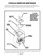
All hydraulic components below the turntable bearing continue to be operable during rotation of the upper assembly
because of the hydraulic collector.  Located on the rotating turntable assembly, the collector is so designed as to
allow the flow of hydraulic oil to the cylinders at all points in the turntable rotation.  (On most
stationary electric machines, an electric collector is used.)

COLLECTOR SHOWN MAY NOT BE TYPE USED ON YOUR MACHINE BUT IS SHOWN AS A REFERENCE.

COLLECTOR SHOWN MAY NOT BE TYPE USED ON YOUR MACHINE BUT IS SHOWN AS A REFERENCE.

COLLECTOR SHOWN MAY NOT BE TYPE USED ON YOUR MACHINE BUT IS SHOWN AS A REFERENCE.

COLLECTOR SHOWN MAY NOT BE TYPE USED ON YOUR MACHINE BUT IS SHOWN AS A REFERENCE.

COLLECTOR SHOWN MAY NOT BE TYPE USED ON YOUR MACHINE BUT IS SHOWN AS A REFERENCE.

SAFETY WIRE

SAFETY WIRE

SAFETY WIRE

SAFETY WIRE

SAFETY WIRE

TORQUE ARM

TORQUE ARM

TORQUE ARM

TORQUE ARM

TORQUE ARM

TORQUE ARM

TORQUE ARM

TORQUE ARM

TORQUE ARM

TORQUE ARM
MOUNTING

MOUNTING

MOUNTING

MOUNTING

MOUNTING
PLATE

PLATE

PLATE

PLATE

PLATE

SEALS

SEALS

SEALS

SEALS

SEALS

SAFETY

SAFETY

SAFETY

SAFETY

SAFETY
WIRE

WIRE

WIRE

WIRE

WIRE

RETAINING

RETAINING

RETAINING

RETAINING

RETAINING
PLATE

PLATE

PLATE

PLATE

PLATE

SCREWS

SCREWS

SCREWS

SCREWS

SCREWS

BARREL

BARREL

BARREL

BARREL

BARREL

SPOOL

SPOOL

SPOOL

SPOOL

SPOOL

SERVICING

SERVICING

SERVICING

SERVICING

SERVICING

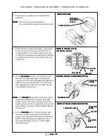
When seals inside collector wear out, a new seal kit must be purchased from your Barko dealer.  (Seal kit numbers
are in parts manual on collector parts list.)  Port numbers are stamped into collector for easy reference.

HYDRAULIC COLLECTOR SEAL KIT INSTRUCTIONS

HYDRAULIC COLLECTOR SEAL KIT INSTRUCTIONS

HYDRAULIC COLLECTOR SEAL KIT INSTRUCTIONS

HYDRAULIC COLLECTOR SEAL KIT INSTRUCTIONS

HYDRAULIC COLLECTOR SEAL KIT INSTRUCTIONS

DISASSEMBLY

DISASSEMBLY

DISASSEMBLY

DISASSEMBLY

DISASSEMBLY
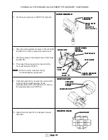
- Remove safety wire and screws from spool retaining plate on top of collector.
- Remove spool from barrel using proper driving equipment, being careful not to damage seal lands or

polished inside diameter of barrel.

- Remove seals from spool by cutting with sharp knife, being careful not to damage spool lands.  If teflon rings are

used, they must be cut off also and the expansion ring under the teflon ring should be replaced (the expansion
ring can be cut off or stretched).

CLEAN AND INSPECT

CLEAN AND INSPECT

CLEAN AND INSPECT

CLEAN AND INSPECT

CLEAN AND INSPECT
- Clean all components thoroughly.
- Inspect for damage to port threads, screw holes and threads, hole elongation, broken spool lands,etc..

Replace or repair damaged components as necessary.

- Barrel with grooves worn deeper than .007 is no longer safely usable.

- Below are four different collector sizes.  Find yours, and be sure that the spool lands on your collector are not

worn deeper than .004 below the standard spool land depth given.  Spool with lands worn deeper than .004 is no
longer safely usable.

(7" spool  O.D. = 6.985 spool land depth)          (5" spool  O.D. = 4.985 spool land depth)
(6" spool  O.D. = 5.985 spool land depth)          (3-1/2" spool O.D. = 3.485 spool land depth)

- Seal grooves of .160 standard width worn beyond .185 at outside diameter are no longer safely usable.
- Grooves of .130 standard width beyond .150 at outside diameter are no longer safely usable.
- Loaded lip seal grooves of .275 standard width worn beyond .325 at outside diameter are no longer safely usable.

Summary of Contents for Crawler 475A

Page 1: ...VICE MANUAL 012501 NOTE The Grapple Service and Installation Information is not included in this manual See separate Grapple Service and Installation manual which accompanies all grapples from the factory BARKO BARKO BARKO BARKO BARKO HYDRAULICS HYDRAULICS HYDRAULICS HYDRAULICS HYDRAULICS LLC LLC LLC LLC LLC mailing POBox16227 Duluth MN 55816 shipping 1BanksAvenue Superior WI 54880 phone 715 392 5...

Page 2: ...aintenance servo 65 Motor Maintenance drive 69 Swing Motor Gearbox Maintenance S10A 70 Swing Brake Maintenance 78 C Electrical System Maintenance C Electrical System Maintenance C Electrical System Maintenance C Electrical System Maintenance C Electrical System Maintenance 82 82 82 82 82 Electrical System Description 83 Electrical System Inspection 83 Using an Extra Battery to Start Machine 83 Alt...

Page 3: ...page 3 page 3 page 3 page 3 page 3 475ACRL 800 00167 Introduction Introduction Introduction Introduction Introduction ...

Page 4: ... each year A professional operator should also be familiar with the information contained in other applicable sources such as American National Standards SAE OSHA etc ADDITIONALINFORMATION Logging Safety Resource Guide APA 95 A 1 is available from the American Pulpwood Association This guide lists sources of videotapes slide programs movies and publications on various aspects of logging safety DON...

Page 5: ...nition Ignition Key Switch Key Switch Key Switch Key Switch Key Switch Power On Power On Power On Power On Power On Accessory Accessory Accessory Accessory Accessory Power Off Power Off Power Off Power Off Power Off Power On Power On Power On Power On Power On Horn Horn Horn Horn Horn Starter Starter Starter Starter Starter Engine Engine Engine Engine Engine RPM RPM RPM RPM RPM Faster Faster Faste...

Page 6: ...sure Other pressure settings may be lower and must be noted may be lower and must be noted may be lower and must be noted may be lower and must be noted may be lower and must be noted In many instances we have learned that the hydraulic relief valves of this equipment have been reset increasing the maximum system pressure and with it the load the unit will lift before the relief valve opens In som...

Page 7: ...ARKO within ten 10 days from the date on which the defect was discovered and any claim submitted within thirty 30 days after repair work is completed BARKO warranty does not cover 1 Defects damage or deterioration due to normal use wear tear exposure storage or corrosion 2 Normal maintenance service including replacement of filters oil seals and the like 3 Damage due to failure to maintain or use ...

Page 8: ...wered to the ground When machine is not operating or when leaving cab boom and attachment must be lowered to the ground When machine is not operating or when leaving cab boom and attachment must be lowered to the ground When machine is not operating or when leaving cab boom and attachment must be lowered to the ground When machine is not operating or when leaving cab boom and attachment must be lo...

Page 9: ...engine before leaving cab If necessary to work engine before leaving cab If necessary to work engine before leaving cab If necessary to work engine before leaving cab If necessary to work engine before leaving cab If necessary to work on machine with lifted boom securely support on machine with lifted boom securely support on machine with lifted boom securely support on machine with lifted boom se...

Page 10: ... WARNING WARNING WARNING WARNING Older air conditioning equipment may contain R 12 Older air conditioning equipment may contain R 12 Older air conditioning equipment may contain R 12 Older air conditioning equipment may contain R 12 Older air conditioning equipment may contain R 12 a substance which harms public health and a substance which harms public health and a substance which harms public he...

Page 11: ...l cause Mechanically connected controls will cause Mechanically connected controls will cause Mechanically connected controls will cause Mechanically connected controls will cause movement of components at all times even if movement of components at all times even if movement of components at all times even if movement of components at all times even if movement of components at all times even if ...

Page 12: ...stion or electrical component damage and may result in death or severe injury damage and may result in death or severe injury damage and may result in death or severe injury damage and may result in death or severe injury damage and may result in death or severe injury This is a 12 volt negative ground electrical This is a 12 volt negative ground electrical This is a 12 volt negative ground electr...

Page 13: ...s brake electrical connections brake electrical connections brake electrical connections brake electrical connections brake systems transmission drivetrain systems transmission drivetrain systems transmission drivetrain systems transmission drivetrain systems transmission drivetrain fuel system and hydraulic system fuel system and hydraulic system fuel system and hydraulic system fuel system and h...

Page 14: ...GHT COUNTERWEIGHT COUNTERWEIGHT COUNTERWEIGHT COUNTERWEIGHT SHROUDING SHROUDING SHROUDING SHROUDING SHROUDING Engine Engine Engine Engine Engine Pumps etc Pumps etc Pumps etc Pumps etc Pumps etc HYDRAULICOIL HYDRAULICOIL HYDRAULICOIL HYDRAULICOIL HYDRAULICOIL RESERVOIR RESERVOIR RESERVOIR RESERVOIR RESERVOIR CAB CAB CAB CAB CAB MAIN BOOM MAIN BOOM MAIN BOOM MAIN BOOM MAIN BOOM CYLINDER CYLINDER CY...

Page 15: ...0 00167 Maintenance Maintenance Maintenance Maintenance Maintenance A PREVENTIVE MAINTENANCE A PREVENTIVE MAINTENANCE A PREVENTIVE MAINTENANCE A PREVENTIVE MAINTENANCE A PREVENTIVE MAINTENANCE Maintenance Maintenance Maintenance Maintenance Maintenance ...

Page 16: ...e injury property damage or structural damage to the injury property damage or structural damage to the injury property damage or structural damage to the machine machine machine machine machine WARNING WARNING WARNING WARNING WARNING Do not support the machine on cinder blocks Do not support the machine on cinder blocks Do not support the machine on cinder blocks Do not support the machine on cin...

Page 17: ...n loader See warnings and instructions both at the beginning and warnings and instructions both at the beginning and warnings and instructions both at the beginning and warnings and instructions both at the beginning and warnings and instructions both at the beginning and throughout this manual After doing service or making repairs throughout this manual After doing service or making repairs throu...

Page 18: ...t 400 hrs thereafter Hydraulic Oil Reservoir Hydraulic Oil Reservoir Hydraulic Oil Reservoir Hydraulic Oil Reservoir Hydraulic Oil Reservoir On new machines oil must be changed after first 50 hours every 1000 hours after that Fittings Fittings Fittings Fittings Fittings Lubricate as shown on Lubrication Points Use a multi purpose grease Bolts Nuts Bolts Nuts Bolts Nuts Bolts Nuts Bolts Nuts Visual...

Page 19: ...d Check for damage and loose or missing bolts Track Roller Guard Track Roller Guard Track Roller Guard Track Roller Guard Track Roller Guard Check for damage and loose or missing bolts Idlers Rollers Idlers Rollers Idlers Rollers Idlers Rollers Idlers Rollers Check for wear leaks near shaft Final Drive Final Drive Final Drive Final Drive Final Drive Change oil after first 100 hours of service ever...

Page 20: ...rs and Carrier Rollers SAE 30 CD TO 2 engine oil Swing Motor Gearbox EP 80 90 gear fluid fill until oil is as high as top of cluster bearings see service manual for more information if lube reservoir is used maintain at half full GREASE GREASE GREASE GREASE GREASE GEAR FLUID OR GEAR FLUID OR GEAR FLUID OR GEAR FLUID OR GEAR FLUID OR ENGINE OIL ENGINE OIL ENGINE OIL ENGINE OIL ENGINE OIL 1 GrappleA...

Page 21: ...se a hand grease gun Rotate the machine slightly between each shot of grease for complete distribution of the grease throughout the Bearing Rotate the machine at least two complete revolutions for each fitting Three shots of grease per fitting should be sufficient on a daily basis Bearing Lubrication Point Bearing Lubrication Point Bearing Lubrication Point Bearing Lubrication Point Bearing Lubric...

Page 22: ...2 NLGI NO 2 NLGI NO 2 NLGI NO 2 NLGI NO 2 HYDRAULIC OIL HYDRAULIC OIL HYDRAULIC OIL HYDRAULIC OIL HYDRAULIC OIL The following lists some features to look for in an oil The hydraulic oil for the machine should feature Rust resistant additives to prevent rust formation from moisture condensation Anti foaming agents to break up air bubbles and prevent foaming that may cause sluggish and erratic opera...

Page 23: ...ulic fluid under pressure can penetrate the skin or eyes Diesel fuel or hydraulic fluid under pressure can penetrate the skin or eyes Diesel fuel or hydraulic fluid under pressure can penetrate the skin or eyes Diesel fuel or hydraulic fluid under pressure can penetrate the skin or eyes Diesel fuel or hydraulic fluid under pressure can penetrate the skin or eyes Fluid leaks under pressure may not ...

Page 24: ...lts and any grade 8 or In critical applications such as Turntable Bearing Bolts and any grade 8 or In critical applications such as Turntable Bearing Bolts and any grade 8 or In critical applications such as Turntable Bearing Bolts and any grade 8 or grade 9 bolts once the old bolts and nuts have been loosened they must grade 9 bolts once the old bolts and nuts have been loosened they must grade 9...

Page 25: ...DRY DRY FINE FINE FINE FINE FINE COARSE COARSE COARSE COARSE COARSE FINE FINE FINE FINE FINE COARSE COARSE COARSE COARSE COARSE DIA DIA DIA DIA DIA LUBRICATED LUBRICATED LUBRICATED LUBRICATED LUBRICATED DRY DRY DRY DRY DRY FINE FINE FINE FINE FINE COARSE COARSE COARSE COARSE COARSE FINE FINE FINE FINE FINE COARSE COARSE COARSE COARSE COARSE LUBRICATED LUBRICATED LUBRICATED LUBRICATED LUBRICATED DR...

Page 26: ...e 26 475ACRL 800 00167 Maintenance Maintenance Maintenance Maintenance Maintenance B HYDRAULIC SYSTEM B HYDRAULIC SYSTEM B HYDRAULIC SYSTEM B HYDRAULIC SYSTEM B HYDRAULIC SYSTEM MAINTENANCE MAINTENANCE MAINTENANCE MAINTENANCE MAINTENANCE ...

Page 27: ...e 27 page 27 page 27 page 27 page 27 475ACRL 800 00167 HYDRAULIC SCHEMATIC HYDRAULIC SCHEMATIC HYDRAULIC SCHEMATIC HYDRAULIC SCHEMATIC HYDRAULIC SCHEMATIC 607 00006 607 00006 607 00006 607 00006 607 00006 ...

Page 28: ...lve pressure setting has been arrived The relief valve pressure setting has been arrived The relief valve pressure setting has been arrived The relief valve pressure setting has been arrived The relief valve pressure setting has been arrived at by our engineers after considerable experience at by our engineers after considerable experience at by our engineers after considerable experience at by ou...

Page 29: ...nder 4800 PSI at the Port Relief Live Heel Boom up rod end of live heel boom cylinder 5600 PSI at the Port Relief Live Heel Boom down butt end of live heel boom cylinder 1850 PSI at the Port Relief Main Reliefs 4600 PSI HYDRAULIC PRESSURE SETTINGS CONTINUED 4800 4800 4800 4800 4800 NONE NONE NONE NONE NONE NONE NONE NONE NONE NONE 3300 3300 3300 3300 3300 NONE NONE NONE NONE NONE MAIN MAIN MAIN MA...

Page 30: ... JAM NUT NUT NUT NUT NUT MAXIMUM MAXIMUM MAXIMUM MAXIMUM MAXIMUM DISPLACEMENT DISPLACEMENT DISPLACEMENT DISPLACEMENT DISPLACEMENT SCREW SCREW SCREW SCREW SCREW Set at Set at Set at Set at Set at factory factory factory factory factory MINIMUM MINIMUM MINIMUM MINIMUM MINIMUM DISPLACEMENT DISPLACEMENT DISPLACEMENT DISPLACEMENT DISPLACEMENT SCREW SCREW SCREW SCREW SCREW BOOM TRAVEL PUMP BOOM TRAVEL P...

Page 31: ...d to mounted to mounted to mounted to servo manifold servo manifold servo manifold servo manifold servo manifold CONTROLLER CONTROLLER CONTROLLER CONTROLLER CONTROLLER SWING PUMP SWING PUMP SWING PUMP SWING PUMP SWING PUMP SERVO PUMP SERVO PUMP SERVO PUMP SERVO PUMP SERVO PUMP CHARGE PRESSURE CHARGE PRESSURE CHARGE PRESSURE CHARGE PRESSURE CHARGE PRESSURE CHECK PORT CHECK PORT CHECK PORT CHECK POR...

Page 32: ...ng screw with a screwdriver all the way in and then back out a quarterturn 13 On the New Style New Style New Style New Style New Style Boom Travel Pumps with machine running and gauges on the pressure check ports raise the compensator setting above 5600 PSI by loosening the jam nut and turning the adjusting screw in with a 3mm Allen wrench Then retighten the jam nut NOTE NOTE NOTE NOTE NOTE On Old...

Page 33: ...LVE RELIEF VALVE RELIEF VALVE RELIEF VALVE TRAVEL COUNTERBALANCE VALVE TRAVEL COUNTERBALANCE VALVE TRAVEL COUNTERBALANCE VALVE TRAVEL COUNTERBALANCE VALVE TRAVEL COUNTERBALANCE VALVE SWING PUMP SWING PUMP SWING PUMP SWING PUMP SWING PUMP SPEED SENSE SPEED SENSE SPEED SENSE SPEED SENSE SPEED SENSE SCREW SCREW SCREW SCREW SCREW MAIN MAIN MAIN MAIN MAIN RAISE RAISE RAISE RAISE RAISE PORT RELIEFS PORT...

Page 34: ...AVEL PUMP NEW STYLE BOOM TRAVEL PUMP NEW STYLE COMPENSATOR COMPENSATOR COMPENSATOR COMPENSATOR COMPENSATOR ADJUSTING ADJUSTING ADJUSTING ADJUSTING ADJUSTING SCREW SCREW SCREW SCREW SCREW JAM NUT JAM NUT JAM NUT JAM NUT JAM NUT THREADED THREADED THREADED THREADED THREADED SLEEVE SLEEVE SLEEVE SLEEVE SLEEVE ADJUSTING ADJUSTING ADJUSTING ADJUSTING ADJUSTING NUT NUT NUT NUT NUT COMPENSATOR COMPENSATOR...

Page 35: ...ENDER CAUTION CAUTION CAUTION CAUTION CAUTION When making repairs on When making repairs on When making repairs on When making repairs on When making repairs on hydraulic system keep all hydraulic system keep all hydraulic system keep all hydraulic system keep all hydraulic system keep all parts clean and remove parts clean and remove parts clean and remove parts clean and remove parts clean and r...

Page 36: ...L SENDER LEVEL SENDER LEVEL SENDER LEVEL SENDER LEVEL SENDER RETURN RETURN RETURN RETURN RETURN FILTERS FILTERS FILTERS FILTERS FILTERS SUCTION SUCTION SUCTION SUCTION SUCTION STRAINERS STRAINERS STRAINERS STRAINERS STRAINERS SHUT OFF SHUT OFF SHUT OFF SHUT OFF SHUT OFF VALVES VALVES VALVES VALVES VALVES DRAINPLUGS DRAINPLUGS DRAINPLUGS DRAINPLUGS DRAINPLUGS CAUTION CAUTION CAUTION CAUTION CAUTION...

Page 37: ...th all the control valves in neutral run the engine until the pump quiets down then add more oil if necessary 4 As an operator works the booms and grapple add more oil as needed to maintain proper level in reservoir This will work the air out of the system and prevent cavitation which is caused by air bubbles in the oil as it passes through a pump 5 Check the oil level again after the loader has b...

Page 38: ... life Filters do not function when elements are clogged with contaminant to the point of bypass Therefore it its important to do three things 1 Check the Filter Indicator frequently to determine when the element needs servicing 2 Make sure the filter is fitted with the correct replacement element The correct replacement element should be listed on the filter nameplate 3 A periodic fluid sample of ...

Page 39: ...GING FILTER ELEMENT 1 Unscrew filter bowl from filter head 2 Replace old element with new one inside filter bowl Screw filter bowl with element inside to filter head CAUTION CAUTION CAUTION CAUTION CAUTION These filter elements are not re usable These filter elements are not re usable These filter elements are not re usable These filter elements are not re usable These filter elements are not re u...

Page 40: ...re not re usable These filter elements are not re usable These filter elements are not re usable These filter elements are not re usable FILTER ELEMENT REPLACEMENT INTERVALS FILTER ELEMENT REPLACEMENT INTERVALS FILTER ELEMENT REPLACEMENT INTERVALS FILTER ELEMENT REPLACEMENT INTERVALS FILTER ELEMENT REPLACEMENT INTERVALS On new machine filter elements should be replaced after 50 hours of operation ...

Page 41: ...tmospheric pressure air may be drawn in where fluid will not necessarily leak out 5 Fluid level too low This can cause vortexing at pump inlet in reservoir thus drawing in air 6 Air trapped in filter with no means of bleed off 7 Return fluid discharged above fluid level in reservoir Poor baffling in the reservoir can also cause turbulence and resultant introduction of air 8 Air trapped in system d...

Page 42: ...nings keep dirt out of tubelines and openings keep dirt out of tubelines and openings keep dirt out of tubelines and openings PIPE THREAD SEALER PIPE THREAD SEALER PIPE THREAD SEALER PIPE THREAD SEALER PIPE THREAD SEALER The main causes of air being introduced into a hydraulic system are loose connections and fittings This not only creates aeration in the fluid but also provides the risk of contam...

Page 43: ... item 8 Heating item 10 7 and the stiff portion of 1 in a 200 oven for 5 minutes will make it more pliable Some kits may contain extra seals When installing the wear rings items 2 6 put the cuts on opposite sides 9 Start gland on rod and hammer on until it is past the stub 10 Slide piston onto stub ensure O ring 3 is on stub and piston is in proper orientation small recess is O ring side large rec...

Page 44: ... 1 1 10 10 10 10 10 MODULAR BACKUP RING MODULAR BACKUP RING MODULAR BACKUP RING MODULAR BACKUP RING MODULAR BACKUP RING 1 1 1 1 1 11 11 11 11 11 O RING O RING O RING O RING O RING 1 1 1 1 1 1 1 1 1 1 3 3 3 3 3 6 6 6 6 6 2 2 2 2 2 7 7 7 7 7 8 8 8 8 8 10 10 10 10 10 9 9 9 9 9 11 11 11 11 11 5 5 5 5 5 4 4 4 4 4 2 2 2 2 2 6 6 6 6 6 NOTE Follow order and orientation of seals shown in drawing Expansion ...

Page 45: ...ual on collector parts list Port numbers are stamped into collector for easy reference HYDRAULIC COLLECTOR SEAL KIT INSTRUCTIONS HYDRAULIC COLLECTOR SEAL KIT INSTRUCTIONS HYDRAULIC COLLECTOR SEAL KIT INSTRUCTIONS HYDRAULIC COLLECTOR SEAL KIT INSTRUCTIONS HYDRAULIC COLLECTOR SEAL KIT INSTRUCTIONS DISASSEMBLY DISASSEMBLY DISASSEMBLY DISASSEMBLY DISASSEMBLY Remove safety wire and screws from spool re...

Page 46: ...ARNING WARNING WARNING Do not heat teflon rings beyond 400 degrees Fahrenheit Do not heat teflon rings beyond 400 degrees Fahrenheit Do not heat teflon rings beyond 400 degrees Fahrenheit Do not heat teflon rings beyond 400 degrees Fahrenheit Do not heat teflon rings beyond 400 degrees Fahrenheit If teflon rings are heated beyond 400 degrees Fahrenheit If teflon rings are heated beyond 400 degrees...

Page 47: ...hould be followed very closely to ensure that the valve bank is properly reassembled after repairs have been made See Figure 1 Figure 1 Figure 1 Figure 1 Figure 1 Figure 1 A Take a waterproof quick drying marker and mark each casting with a sequential number Start by marking the inlet casting as 1 and finish by marking the outlet with the highest number B Then mark the port boss closest to the bac...

Page 48: ... poppet sleeve Item 17 Figure 3 4 unless it is to be serviced Next poppet sleeve Item 17 Figure 3 4 unless it is to be serviced Next remove the two retainer screws Item 9 from the spool clevis end of remove the two retainer screws Item 9 from the spool clevis end of remove the two retainer screws Item 9 from the spool clevis end of remove the two retainer screws Item 9 from the spool clevis end of...

Page 49: ...eyneedtobereplaced Oncethespoolisfreeoftheworksection housing it must be handled carefully to avoid damage Place the spool in a soft jawed vise and remove the stripper bolt Item 14 with a wrench Cautious application of heat may be required to free the stripper bolt because an anaerobic thread adhesive is used in its assembly CAUTION CAUTION CAUTION CAUTION CAUTION TOO MUCH HEAT MAY DISTORT THE SPO...

Page 50: ...ies Section Seals See Figure 2 1 SquareSeal 2 3 SquareSeal 1 Parallel and Series Section Component Parts See Figure 3 4 4 Back Cap Screw 2 5 Back Cap 1 6 RetainerPlate 3 7 Backup Ring 2 8 Spool Seal 2 9 Retainer Plate Screw 2 10 Check Valve Cap 1 Or Valve Cap F I N 1 11 O RingSeal 1 12 CheckSpring 1 13 Check Valve Poppet 1 14 Stripper Bolt 1 15 CenteringSpring 1 16 SpringGuide 2 17 Detent Sleeve 1...

Page 51: ...2 extends across the o ring face of the valve housing extends across the o ring face of the valve housing extends across the o ring face of the valve housing extends across the o ring face of the valve housing extends across the o ring face of the valve housing It should not be stoned or ground off It should not be stoned or ground off It should not be stoned or ground off It should not be stoned ...

Page 52: ...sult in assembly failure prepare parts properly may result in assembly failure Then lightly coat the detent balls Item 18 detent spring Item 19 and detent sleeve Item 17 with high temperaturegrease Next place the detent balls and spring into the detent poppet retainer as shown in Step 8 and partially compress them with a small clamp Now slide the detent sleeve into position pushing the clamp out o...

Page 53: ...opriate machining NOTE NOTE NOTE NOTE NOTE When installing relief valves torque them to 80 90 ft lbs ITEM ITEM ITEM ITEM ITEM DESCRIPTION DESCRIPTION DESCRIPTION DESCRIPTION DESCRIPTION QTY QTY QTY QTY QTY 1 O RING 2 2 O RING 1 3 BACKUPRING 1 4 GASKET WASHER 1 Figure 5 Figure 5 Figure 5 Figure 5 Figure 5 A20 A35 CONTROL VALVE MAINTENANCE CONTINUED SYSTEM OVERLOAD RELIEF VALVE SYSTEM OVERLOAD RELIE...

Page 54: ...PARATION OF PARTS PREPARATION OF PARTS PREPARATION OF PARTS PREPARATION OF PARTS 1 Clean adhesive from threads of spool stripper bolt housing cap screw holes and hex nut with Loctite Chisel GasketRemover 2 Wash all parts in solvent to remove grease and oil Blow dry SECTION ASSEMBLY SECTION ASSEMBLY SECTION ASSEMBLY SECTION ASSEMBLY SECTION ASSEMBLY SEE FIGURE 8 CAUTION CAUTION CAUTION CAUTION CAUT...

Page 55: ...seals Seals are similar in size Be sure to insert seals Seals are similar in size Be sure to insert seals Seals are similar in size Be sure to insert seals 1 10 in their proper position They are not 1 10 in their proper position They are not 1 10 in their proper position They are not 1 10 in their proper position They are not 1 10 in their proper position They are not interchangeable interchangeab...

Page 56: ...d seat Scored or sticking check valve poppet Disassemble clean reassemble Replacepoppet No motion slow or erratic system operation Wornpump Defective cylinder or motor Low reservoir oil level Clogged suction strainer Suction line restricted Relief valve not properly set Relief valve poppet or seat scored sticking Valve spool not shifted to full stroke Check flow pressure Repairorreplace Add oil to...

Page 57: ...aw pinion shaft and inspect gear teeth and bearing surfaces for abnormal wear Torque values for bolts when replacing charge pump are as follows PUMP SIZE TORQUE in lb 40 220 56 220 90 220 125 440 If serious wear or damage has occured to one componenet in charge pump complete charge pump assembly must be replaced because components are a matched set REPLACEMENT OF SHAFT SEAL REPLACEMENT OF SHAFT SE...

Page 58: ...AND COMPONENT SEAL KITS AND COMPONENT SEAL KITS AND COMPONENT SEAL KITS AND COMPONENT SEAL KITS AND COMPONENT GROUPS GROUPS GROUPS GROUPS GROUPS 1 Seal kit for Drive Shaft 2 Complete seal kit 3 Subplate with control cylinder 4 Rotarygroup SEALING THE DRIVESHAFT SEALING THE DRIVESHAFT SEALING THE DRIVESHAFT SEALING THE DRIVESHAFT SEALING THE DRIVESHAFT 1 Tape up driveshaft remove retaining ring and...

Page 59: ... o ring 2 o ring groove 3 running area 4 and o ring contact area 5 4 Fit the shaft seal dry with insertion sleeve 1 Use shim 2 only if running groove is deep 5 Fill the space between the dust and sealing lip 1 with grease 6 Retaining ring 1 end ring 2 shaft seal 4 o ring 5 BOOM TRAVEL PUMP MAINTENANCE CONTINUED ...

Page 60: ... the chamfer 2 8 O ring behind thread or recess Tape up recess or thread SEALING THE CONTROL DEVICE SEALING THE CONTROL DEVICE SEALING THE CONTROL DEVICE SEALING THE CONTROL DEVICE SEALING THE CONTROL DEVICE 1 Control Device spring side Remove from subplate 2 Inspect the sealing face 1 groove 2 and o ring 3 3 Control Device piston side Mark cover and housing 1 and remove from subplate BOOM TRAVEL ...

Page 61: ...NG THE SUBPLATE SEALING THE SUBPLATE SEALING THE SUBPLATE SEALING THE SUBPLATE SEALING THE SUBPLATE 1 Mark position 1 DO NOT USE A SCREWDRIVER TO DISMANTLE THE SEALING FACE Disassemble from inside the suction port 2 2 Inspect the sublplate sealing face 1 gasket 2 and housing sealing face 3 3 Inspect cylinder running areas 1 and lens sliding surfaces 2 Do not remove cylinder BOOM TRAVEL PUMP MAINTE...

Page 62: ... flat No fluid seal seal thickness has been allowed for in the rotary groupadjustment Reassemblesubplate REPLACING THE ROTARY GROUP REPLACING THE ROTARY GROUP REPLACING THE ROTARY GROUP REPLACING THE ROTARY GROUP REPLACING THE ROTARY GROUP 1 Remove the subplate as described earlier 2 Remove cylinder 1 with four cup springs 2 and spring washer 3 3 Remove shaft seal and back up washer BOOM TRAVEL PU...

Page 63: ...ted and that the housing is not damaged 6 Check that lens sliding surface 1 is free of scoring and not worn 7 Reassemble rotary group and shaft seal and back up washer by heating the housing to approximately 80 degrees Celsius and inserting rotarygroup 8 Draw rotary group against retaining ring BOOM TRAVEL PUMP MAINTENANCE CONTINUED ...

Page 64: ...page 64 page 64 page 64 page 64 page 64 475ACRL 800 00167 9 Reassemble subplate onto housing BOOM TRAVEL PUMP MAINTENANCE CONTINUED ...

Page 65: ...y Qty Qty Qty Description Description Description Description Description Item Item Item Item Item Qty Qty Qty Qty Qty Figure A Figure A Figure A Figure A Figure A PREPARATION FOR DISASSEMBLY PREPARATION FOR DISASSEMBLY PREPARATION FOR DISASSEMBLY PREPARATION FOR DISASSEMBLY PREPARATION FOR DISASSEMBLY Overhaul pump only in a clean dust free location using clean tools and equipment Dirt or grit wi...

Page 66: ...r into pump body more than At no time should screwdrivers be inserted further into pump body more than At no time should screwdrivers be inserted further into pump body more than At no time should screwdrivers be inserted further into pump body more than depth of relieved areas Any burr must be removed from body and or cover depth of relieved areas Any burr must be removed from body and or cover d...

Page 67: ...EASSEMBLY PUMP REASSEMBLY PUMP REASSEMBLY PUMP REASSEMBLY PUMP REASSEMBLY NOTE NOTE NOTE NOTE NOTE The installation of new parts contained in seal kit are recommended at each overhaul of pump 1 Place body on flat plate with shaft seal bore up See Figure 1 Install new shaft seal Press seal into bore to depth of approximately 1 16 1 52 mm with a seal pressing tool Pack area between double lip of sea...

Page 68: ...in wipe chips If a new body is installed break in of pump will result in wipe chips If a new body is installed break in of pump will result in wipe chips If a new body is installed break in of pump will result in wipe chips which is normal to be expelled from pump outlet These small aluminum which is normal to be expelled from pump outlet These small aluminum which is normal to be expelled from pu...

Page 69: ...e o ring and shaft seal from front cover and dispose of them 4 Lubricate new o ring and shaft seal 5 Replace front cover with new shaft seal and o ring preassembled 6 Replace front cover mounting bolts and tighten front cover to housing MOTOR MAINTENANCE DRIVE MOTOR MAINTENANCE DRIVE MOTOR MAINTENANCE DRIVE MOTOR MAINTENANCE DRIVE MOTOR MAINTENANCE DRIVE Figure 2 Figure 2 Figure 2 Figure 2 Figure ...

Page 70: ...ion briefly outlines what to look for when performing these tests THE ROLL TEST THE ROLL TEST THE ROLL TEST THE ROLL TEST THE ROLL TEST The purpose of a roll test is to determine if the unit s gears are rotating freely and properly You should be able to rotate the gears in your unit by applying a constant force to the roll checker If you feel more drag in the gears only atcertainpoints thenthegear...

Page 71: ...LLPIN 3C 6 BEARINGCUP 3D 6 BEARINGCONE ITEM ITEM ITEM ITEM ITEM QTY QTY QTY QTY QTY DESCRIPTION DESCRIPTION DESCRIPTION DESCRIPTION DESCRIPTION 3E 3 PLANET SHAFT 3F 3 CLUSTERGEAR 3G 3 SPACER 3H 3 RETAININGRING 4 1 RINGGEAR 5 2 O RING 6 1 COVER 6I 2 MAGNETIC PIPE PLUG 8 1 THRUSTWASHER 13 1 INPUT GEAR 15 4 THRUSTWASHER 16 2 THRUSTBEARING 17 16 BOLT 18 4 SHOULDERBOLT 22 4 LOCKWASHER 23 16 LOCKWASHER ...

Page 72: ... Remove o ring 5 from the counterbore around rim of hub 1G 10 Remove pipe plug 1L from hub 1G 11 Remove internal gear 2 from hub 1G using hoist 12 Using hammer and punch knock lock washer 1I tang out of slot of lock nut 1J 13 Loosen lock nut 1J using lock nut wrench 14 Remove lock nut 1J from shaft 1A 15 Remove lock washer 1I from shaft 1A 16 Remove tanged washer 1H from shaft 1A 17 Press output s...

Page 73: ...this step 10 Drive the roll pin 3B into its hole in carrier 3A Use a punch to drive roll pin flush to carrier surface 3A 11 Measure the end play of the cluster gear 3F with a dial indicator Pry up on the bottom of the cluster gear to get the reading The reading should not exceed 003 If it does contact the manufacturer 12 After getting a reading of 001 002 or 003 use a stamp and stamp 1 for 001 2 f...

Page 74: ... step 12 Spray output 1A threads with Primer T Allow two to three minutes drying time 13 Spray lock nut 1J with Primer T Allow two to three minutes drying time 14 Place tanged washer 1H over the output shaft 1A and against the bearing cone 1F with the tang in the groove 15 Place lock washer 1I over the output shaft 1A with the tang facing away from the bearing cone 1F Make sure the tang is in the ...

Page 75: ...shoulder of output shaft 1A 12 Place thrust bearing 16 onto thrust washer 15 13 Place thrust washer 15 over thrust bearing 16 14 Set input gear 13 onto the output shaft 1A 15 Apply grease to o ring 5 16 Place greased o ring 5 into the counterbore of hub 1G 17 Place the input carrier 3 on a flat surface Locate gear teeth with a punch mark on them Place all teeth with a punch mark on them to 12 o cl...

Page 76: ...PART TWO MAIN ASSEMBLY PART TWO MAIN ASSEMBLY PART TWO MAIN ASSEMBLY PART TWO 1 Using hoist place cover 6 onto ring gear 4 Rotate cover until both pipe plugs 6I are located in line with marked location of pipe plugs 1N on shaft side of hub See Diagram 4 Pipe plug timing 2 Put lock washers 22 over shoulder bolt holes on hub 3 Put in four shoulder bolts 18 and tighten 4 Put lock washer 23 over bolt ...

Page 77: ...3 minutes 12 At this point the main assembly is complete FILLING WITH OIL AND OIL FILLING WITH OIL AND OIL FILLING WITH OIL AND OIL FILLING WITH OIL AND OIL FILLING WITH OIL AND OIL CHANGE INTERVALS CHANGE INTERVALS CHANGE INTERVALS CHANGE INTERVALS CHANGE INTERVALS For normal applications use EP90 gear fluid Fill until oil is as high as top of cluster bearings see illustration at right Check oil ...

Page 78: ...nting flange Ensure that the bolts are not too long so that they do not bottom out in the gearbox before clamping 7 Run bolts in alternately to prevent binding until snug Then torque the bolts to 75 85 lb ft NOTE NOTE NOTE NOTE NOTE Both shafts must slide together freely DO NOT use bolts to force the unit together 8 With motor and brake bolted into position remove cap plug and connect inlet hydrau...

Page 79: ...Springs 7 andRetainer 6 4 Remove Seal 1 The seal will be destroyed by the removal process and must be replaced if removed CAUTION CAUTION CAUTION CAUTION CAUTION Be careful not to damage the adjacent bearing seal Be careful not to damage the adjacent bearing seal Be careful not to damage the adjacent bearing seal Be careful not to damage the adjacent bearing seal Be careful not to damage the adjac...

Page 80: ...LY PROCEDURE 1 All parts must be thoroughly clean prior to re assembly 2 IMPORTANT IMPORTANT IMPORTANT IMPORTANT IMPORTANT There may be more parts in a service kit than your brake requires Check parts list care fully for the exact quantity In the case of springs space the required quantity equally 3 Generally use the reverse of the disassembly procedure to re assemble the brake 4 Cylinder of the p...

Page 81: ... until Power Plate 20 is properly seated Torque to 75 85 lb ft Then press Bearing 3 onto Shaft 9 8 Rotating discs must be clean and dry There should be no presence of oil on any lining material or mating surfaces of the stationary discs Worn or heavily scored rotating discs must be replaced 9 If replacement of Oil Relief Plug 23 is necessary replace while Power Plate 20 is disassembled Insert Plug...

Page 82: ...2 475ACRL 800 00167 Maintenance Maintenance Maintenance Maintenance Maintenance C ELECTRICAL SYSTEM C ELECTRICAL SYSTEM C ELECTRICAL SYSTEM C ELECTRICAL SYSTEM C ELECTRICAL SYSTEM MAINTENANCE MAINTENANCE MAINTENANCE MAINTENANCE MAINTENANCE ...

Page 83: ...USING AN EXTRA BATTERY TO START MACHINE USING AN EXTRA BATTERY TO START MACHINE If necessary to use an extra battery and jumper cables to start engine be careful This is a two person operation There must be one person in operator s seat and one person to connect and disconnect battery cables WARNING WARNING WARNING WARNING WARNING Lead acid batteries produce flammable and explosive gases Keep arcs...

Page 84: ...ry acid contact wash immediately with water and seek immediate medical attention acid contact wash immediately with water and seek immediate medical attention acid contact wash immediately with water and seek immediate medical attention acid contact wash immediately with water and seek immediate medical attention acid contact wash immediately with water and seek immediate medical attention 7 Check...

Page 85: ...lled it will be necessary to adjust it after 8 hours of machine operation Adjusting Belt Tension Adjusting Belt Tension Adjusting Belt Tension Adjusting Belt Tension Adjusting Belt Tension 1 2 of movement 1 2 of movement 1 2 of movement 1 2 of movement 1 2 of movement BELT BELT BELT BELT BELT ADJUSTINGBOLT ADJUSTINGBOLT ADJUSTINGBOLT ADJUSTINGBOLT ADJUSTINGBOLT ADJUSTMENTBAR ADJUSTMENTBAR ADJUSTME...

Page 86: ... percent of rated amperage check regulator CHECKINGTHEREGULATOR CHECKINGTHEREGULATOR CHECKINGTHEREGULATOR CHECKINGTHEREGULATOR CHECKINGTHEREGULATOR 1 Use steps 1 through 5 of Checking Alternator Output 2 Put a small screwdriver in test hole See Figure 3 Alternator Alternator Alternator Alternator Alternator No 2 terminal No 2 terminal No 2 terminal No 2 terminal No 2 terminal No 1 terminal No 1 te...

Page 87: ...lt is loose or damaged 2 Battery connections are dirty of loose 3 Battery is damaged 4 The ground connection is not making a good contact 5 The alternator is damaged 6 The engine is locked 7 The starter has damage 8 The wiring or the solenoid is damaged ELECTRICAL SYSTEM TROUBLE SHOOTING ELECTRICAL SYSTEM TROUBLE SHOOTING ELECTRICAL SYSTEM TROUBLE SHOOTING ELECTRICAL SYSTEM TROUBLE SHOOTING ELECTR...

Page 88: ... 88 page 88 page 88 475ACRL 800 00167 Maintenance Maintenance Maintenance Maintenance Maintenance D POWER UNIT MAINTENANCE D POWER UNIT MAINTENANCE D POWER UNIT MAINTENANCE D POWER UNIT MAINTENANCE D POWER UNIT MAINTENANCE ...

Page 89: ...ng instructions and maintenance and lubrication information will be found in the Cummins engine manuals which accompanies the machine Either of these manuals may also include information on other similar engines Be sure to use only the information which applies to the engine used on your machine ENGINE MAINTENANCE ENGINE MAINTENANCE ENGINE MAINTENANCE ENGINE MAINTENANCE ENGINE MAINTENANCE ...

Page 90: ... level be checked daily at the same time checking for fluid leaks Because the lubricant system is the heart of the unit it is especially important that the fluid be kept clean The following procedures should be followed 1 Stop engine before checking or adding fluid 2 Check unit for operational warning tags Heed all warnings 3 Clean around fluid fill before checking or adding fluid 4 Change the flu...

Page 91: ...n gear and bearings from pump drive box 7 Should replacement of oil seal be required drive oil seal toward engine side of engine adaptor 1 1 1 1 1 ENGINE ENGINE ENGINE ENGINE ENGINE 2 2 2 2 2 FLYWHEEL COVER FLYWHEEL COVER FLYWHEEL COVER FLYWHEEL COVER FLYWHEEL COVER 3 3 3 3 3 ENGINEADAPTOR ENGINEADAPTOR ENGINEADAPTOR ENGINEADAPTOR ENGINEADAPTOR 4 4 4 4 4 PUMP DRIVE PUMP DRIVE PUMP DRIVE PUMP DRIVE...

Page 92: ...bolt or stud hole location which will be used for a bolt or stud hole location which will be used for a bolt or stud fastener Do not lap ends behind an unused bolt hole fastener Do not lap ends behind an unused bolt hole fastener Do not lap ends behind an unused bolt hole fastener Do not lap ends behind an unused bolt hole fastener Do not lap ends behind an unused bolt hole Remove protective paper...

Page 93: ...r s Manual Example of a Pump Drive with a Disconnect Clutch Example of a Pump Drive with a Disconnect Clutch Example of a Pump Drive with a Disconnect Clutch Example of a Pump Drive with a Disconnect Clutch Example of a Pump Drive with a Disconnect Clutch HAND HOLE PLATE HAND HOLE PLATE HAND HOLE PLATE HAND HOLE PLATE HAND HOLE PLATE Pull pin in this Pull pin in this Pull pin in this Pull pin in t...

Page 94: ...e is working See Figure 1 NOTE NOTE NOTE NOTE NOTE This is especially important in the fall months as the trees shed their leaves AIR CLEANER BONNET AIR CLEANER BONNET AIR CLEANER BONNET AIR CLEANER BONNET AIR CLEANER BONNET Figure 1 Figure 1 Figure 1 Figure 1 Figure 1 Figure 2 Figure 2 Figure 2 Figure 2 Figure 2 DUSTCUP DUSTCUP DUSTCUP DUSTCUP DUSTCUP ARROWS ARROWS ARROWS ARROWS ARROWS DUSTCUP DU...

Page 95: ...iction tap provided in the Air Cleaner the transfer pipe or the blower intake Replace the element only when the restriction has reached the maximum allowed by the engine manufacturer Contact the Barko Service Department for maximum values and any other questions concerning this method CAUTION CAUTION CAUTION CAUTION CAUTION Check the Air Cleaner Assembly daily for cracks Check the Air Cleaner Asse...

Page 96: ... replacing the element 5 5 5 5 5 PRESS YOUR PRESS YOUR PRESS YOUR PRESS YOUR PRESS YOUR FRESH GASKET FRESH GASKET FRESH GASKET FRESH GASKET FRESH GASKET TO SEE IF IT TO SEE IF IT TO SEE IF IT TO SEE IF IT TO SEE IF IT SPRINGS BACK SPRINGS BACK SPRINGS BACK SPRINGS BACK SPRINGS BACK Make sure your new element is made with a highly compressible gasket that springs right back when your finger pressur...

Page 97: ...d immediately cover the opening The only way to be sure nothing got in is to be sure nothing gets in THE IMPORTANT DON TS TO ALWAYS REMEMBER THE IMPORTANT DON TS TO ALWAYS REMEMBER THE IMPORTANT DON TS TO ALWAYS REMEMBER THE IMPORTANT DON TS TO ALWAYS REMEMBER THE IMPORTANT DON TS TO ALWAYS REMEMBER DON T DON T DON T DON T DON T OVERLOOK A OVERLOOK A OVERLOOK A OVERLOOK A OVERLOOK A WORN OR WORN O...

Page 98: ...800 00167 Maintenance Maintenance Maintenance Maintenance Maintenance E CAT 330 CRAWLER LOWER E CAT 330 CRAWLER LOWER E CAT 330 CRAWLER LOWER E CAT 330 CRAWLER LOWER E CAT 330 CRAWLER LOWER MAINTENANCE MAINTENANCE MAINTENANCE MAINTENANCE MAINTENANCE ...

Page 99: ...one turn only CAUTION CAUTION CAUTION CAUTION CAUTION If the dimension between the end of the track roller frame and the flange If the dimension between the end of the track roller frame and the flange If the dimension between the end of the track roller frame and the flange If the dimension between the end of the track roller frame and the flange If the dimension between the end of the track roll...

Page 100: ...vel Plug Figure 1 Figure 1 Figure 1 Figure 1 Figure 1 3 Oil should be to the bottom of the oil level plug opening 4 Add oil through the opening of the oil level plug if necessary 5 Clean oil level plug Inspect the O RING seal Replace it if it is worn or damaged 6 Install the oil level plug 7 Repeat procedure on the other final drive FINAL DRIVES CHANGING THE FINAL DRIVES CHANGING THE FINAL DRIVES ...

Page 101: ...ge 101 page 101 page 101 475ACRL 800 00167 Structural Structural Structural Structural Structural F STRUCTURAL MAINTENANCE F STRUCTURAL MAINTENANCE F STRUCTURAL MAINTENANCE F STRUCTURAL MAINTENANCE F STRUCTURAL MAINTENANCE ...

Page 102: ...a bearing is pitting or spalling small metal particles in the grease operation changes from smooth to rough an increase in necessary drive power noise a steady increase of bearing clearance which accelerates towards the end of the bearing life The last item bearing clearance can be measured and is a good means of determining the bearing condition MEASURING BEARING CLEARANCE MEASURING BEARING CLEAR...

Page 103: ...ators and record the measurements 7 Elevate the boom back to the neutral position dial indicator should return to zero 8 Rotate the upper works to the next measurement location and take readings the same as above Figure 1 Figure 1 Figure 1 Figure 1 Figure 1 Possible Indicator Position Possible Indicator Position Possible Indicator Position Possible Indicator Position Possible Indicator Position Di...

Page 104: ...4 134 134 130 130 130 130 130 102 102 102 102 102 110 110 110 110 110 126 126 126 126 126 130 130 130 130 130 134 134 134 134 134 138 138 138 138 138 140 140 140 140 140 114 114 114 114 114 126 126 126 126 126 134 134 134 134 134 136 136 136 136 136 138 138 138 138 138 150 150 150 150 150 118 118 118 118 118 130 130 130 130 130 138 138 138 138 138 140 140 140 140 140 142 142 142 142 142 160 160 16...

Page 105: ... BEARING MOUNTING BOLT TORQUE BEARING MOUNTING BOLT TORQUE Check bearing mounting bolts for proper torque every 50 hours of operation Torque to proper amount given in Special Torque Specifications section of machine s Operator s Manual WARNING WARNING WARNING WARNING WARNING Loose or overtorqued bolts can cause death severe injury or property damage Loose or overtorqued bolts can cause death sever...

Page 106: ...page 106 page 106 page 106 page 106 page 106 475ACRL 800 00167 Trouble Shooting Trouble Shooting Trouble Shooting Trouble Shooting Trouble Shooting ...

Page 107: ...vel Check for and repair any leaks Drain engine oil and fill with heavier weight engine oil Engineoverheats Low coolant level Loose worn or broken fan belt Radiatorplugged Air filter elements plugged Fill to correct level and check for leaks Tighten or replace belt Clean and inspect radiator Clean or replace elements Engine will not start Low or discharged battery Rechargebattery ENGINE ENGINE ENG...

Page 108: ...y Oil cooler dirty Relief valve improperly adjusted Incorrect hydraulic oil viscosity Excessive load Pump not receiving hydraulic oil Damagedline Any or all of the following Replace dirty filters Clogged inlet line Cleanreservoirbreather vent Fill reservoir to proper level Replaceline Hydraulic system pressure too low External leak in system Tighten connections and bleed air from system Hydraulicp...

Page 109: ...belts Clean and tighten battery connections Tighten or replace belts Starter will not work or cranks slowly Loose or corroded connections Wrongengineoil Clean and tighten connections Replace engine oil Refer to Fuel Fuel Fuel Fuel Fuel and Lubricants and Lubricants and Lubricants and Lubricants and Lubricants Gauges do not work Gauge sender needs service Loosegaugegroundconnection Replacesender Ch...

Page 110: ...rvice No steering control if applicable Leakage or blockage in hydraulic system Carrier system not operational Repair or replace sources of leaks and blocks Repair or replace as needed Machine steering in opposite direction if applicable Lines to cylinders connected to wrong ports at steering valve or cylinder Correctconnections Steering wheel does not turn if applicable Binding in steering column...

Page 111: ...motor needs service Replace lines Adjust per specifications Repair or replace track drive motor Replace lines Adjust per specifications Repair or replace track drive motor Slow response to track travel foot pedals Machine will not turn on one direction Damaged or broken foot pedal valve Relief valve needs service Repair or replace foot pedal valve Repair or replace valve TROUBLE SHOOTING CONTINUED...

Page 112: ...aged illegible or otherwise damaged illegible or otherwise damaged illegible or otherwise damaged illegible or otherwise damaged WARNING WARNING WARNING WARNING WARNING Do not reproduce any decals listed or shown here for Do not reproduce any decals listed or shown here for Do not reproduce any decals listed or shown here for Do not reproduce any decals listed or shown here for Do not reproduce an...

Reviews: