page 66
page 66
page 66
page 66
page 66
475 A CRL
800-00167
SERVO PUMP MAINTENANCE CONTINUED...
DISASSEMBLY OF PUMP
DISASSEMBLY OF PUMP
DISASSEMBLY OF PUMP
DISASSEMBLY OF PUMP
DISASSEMBLY OF PUMP
1. Clean outside of pump with a good grade solvent and dry thoroughly.
2. On models with splined drive shaft, proceed to step 3.
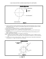
3. Secure unit in vise (use light clamping pressure) with shaft end down; remove cap screws and washers.
NOTE:
NOTE:
NOTE:
NOTE:
NOTE: During disassembly, take special note of wear patterns on wear plate, thrust plate, and body. Relate these
patterns to inlet and outlet sides of pump. Large port in rear cover always corresponds to inlet side of pump. Inlet side
can be further identified by gear contact pattern in body (gear) bore. Wear plate will have a somewhat heavier wear
pattern on inlet side. Thrust plate will also have a pattern that can be established for reassembly. Also note that long
journal of driven gear is toward front of pump.
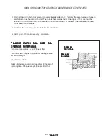
4. Separate rear cover from body by supporting pump, shaft end up, on mounting flanges and pressing on drive shaft
end in arbor press, or tap drive shaft with a plastic mallet.
CAUTION
CAUTION
CAUTION
CAUTION
CAUTION
Use on hand to support rear cover from underneath, since cover and internal
Use on hand to support rear cover from underneath, since cover and internal
Use on hand to support rear cover from underneath, since cover and internal
Use on hand to support rear cover from underneath, since cover and internal
Use on hand to support rear cover from underneath, since cover and internal
parts will drop suddenly when dowels are disengaged.
parts will drop suddenly when dowels are disengaged.
parts will drop suddenly when dowels are disengaged.
parts will drop suddenly when dowels are disengaged.
parts will drop suddenly when dowels are disengaged.
An alternate method of removing rear cover is to pry simultaneously with two large screwdrivers in relieved areas
between body and cover.
CAUTION
CAUTION
CAUTION
CAUTION
CAUTION
At no time should screwdrivers be inserted further into pump body more than
At no time should screwdrivers be inserted further into pump body more than
At no time should screwdrivers be inserted further into pump body more than
At no time should screwdrivers be inserted further into pump body more than
At no time should screwdrivers be inserted further into pump body more than
depth of relieved areas. Any burr must be removed from body and/or cover
depth of relieved areas. Any burr must be removed from body and/or cover
depth of relieved areas. Any burr must be removed from body and/or cover
depth of relieved areas. Any burr must be removed from body and/or cover
depth of relieved areas. Any burr must be removed from body and/or cover
after this operation to assure a good seal between body and cover.
after this operation to assure a good seal between body and cover.
after this operation to assure a good seal between body and cover.
after this operation to assure a good seal between body and cover.
after this operation to assure a good seal between body and cover.
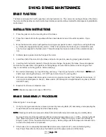
5. Holding pump shaft end down, remove rear cover. Dowel pins may remain either with body or rear cover.
NOTE:
NOTE:
NOTE:
NOTE:
NOTE: Cover gasket and thrust plate may or may not remain with rear cover. Should they remain with body, remove
gasket and lift out thrust plate before proceeding.
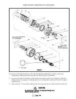
6. Lift out driven gear, drive gear, and wear plate.
7. Invert pump body with shaft seal up. Remove shaft seal by prying it out with a large screwdriver.
CAUTION
CAUTION
CAUTION
CAUTION
CAUTION
Care should be taken not to damage (gouge) shaft seal bore, because this will
Care should be taken not to damage (gouge) shaft seal bore, because this will
Care should be taken not to damage (gouge) shaft seal bore, because this will
Care should be taken not to damage (gouge) shaft seal bore, because this will
Care should be taken not to damage (gouge) shaft seal bore, because this will
result in shaft seal leakage.
result in shaft seal leakage.
result in shaft seal leakage.
result in shaft seal leakage.
result in shaft seal leakage.
PARTS INSPECTION
PARTS INSPECTION
PARTS INSPECTION
PARTS INSPECTION
PARTS INSPECTION
1. Wash all parts and dry thoroughly.
2. Inspect wear plate and thrust plate. Replace if scoring or uneven wear is observed.
NOTE:
NOTE:
NOTE:
NOTE:
NOTE: Somewhat heavier wear pattern is normal on low pressure (inlet) side of plates. However, there should be no
heavy scoring in this area.


