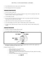
page 73
page 73
page 73
page 73
page 73
475 A CRL
800-00167
S10A SWING MOTOR GEARBOX MAINTENANCE CONTINUED...
CARRIER SUB-ASSEMBLY
CARRIER SUB-ASSEMBLY
CARRIER SUB-ASSEMBLY
CARRIER SUB-ASSEMBLY
CARRIER SUB-ASSEMBLY
1.
Place cluster gear (3F) onto your work surface, either side up. Press bearing cup (3C) into one side of
cluster gear using cup pressing tool.
2.
Turn cluster gear (3F) over onto it’s other side. Press other bearing cup (3C) into other side of cluster
gear (3F) using cup pressing tool.
3.
Place one bearing cone (3D) into one bearing cup (3C) on each end of cluster gear (3F).
4.
Place the carrier (3A) on the edge of the table with one set of holes hanging over the edge. The side with
the small roll pin (3B) hole in the side should be down.
5.
Place cluster gear assembly with bearings (3F) into carrier (3A) with large gear end up.
6.
Slide planet shaft (3E), small end up, into holes through carrier (3A) and cluster gear (3F), from the
bottom.
7.
While holding planet shaft (3E) in position, slide the correct spacer (3G) onto the planet shaft (3E).
CAUTION
CAUTION
CAUTION
CAUTION
CAUTION
Safety glasses should be worn during this step.
Safety glasses should be worn during this step.
Safety glasses should be worn during this step.
Safety glasses should be worn during this step.
Safety glasses should be worn during this step.
8.
Place carrier (3A) all the way onto the table or work surface and put something under the planet shaft
(3E) to hold it in position while installing the retaining ring (3H). Use retaining ring pliers to install retain-
ing ring.
9.
Line up roll pin (3B) hole in the carrier (3A) and planet shaft slot (3E).
CAUTION
CAUTION
CAUTION
CAUTION
CAUTION
Safety glasses should be worn during this step.
Safety glasses should be worn during this step.
Safety glasses should be worn during this step.
Safety glasses should be worn during this step.
Safety glasses should be worn during this step.
10. Drive the roll pin (3B) into its hole in carrier (3A). Use a punch to drive roll pin flush to carrier surface
(3A).
11 .Measure the end play of the cluster gear (3F) with a dial indicator. Pry up on the bottom of the cluster
gear to get the reading. The reading should not exceed .003. If it does, contact the manufacturer.
12. After getting a reading of .001, .002, or .003, use a stamp and stamp 1 (for .001), 2 (for .002), or 3 (for
.003) next to the cluster gear (3F) on carrier so others will know what the dial reading was.
13. Repeat steps 1 to 12 for two remaining cluster gears.
14. At this time, the carrier subassembly is complete.
HUB-SHAFT SUB-ASSEMBLY
HUB-SHAFT SUB-ASSEMBLY
HUB-SHAFT SUB-ASSEMBLY
HUB-SHAFT SUB-ASSEMBLY
HUB-SHAFT SUB-ASSEMBLY
1.
Place output shaft (1A) on work surface with the threaded end up.
2.
Using cone pressing tool press the large end of bearing cone (1D) against the shoulder of output shaft
(1A).
NOTE:
NOTE:
NOTE:
NOTE:
NOTE: Bearing cone may be heated so it can be slipped on, but do NOT exceed 250 degrees F. Once
bearing cone has cooled, make sure it is against the output shaft shoulder.
3.
Place hub (1G) with it’s small end up on the work surface.
4.
Using cup pressing tool press bearing cup (1C) into the hub counterbore.
5.
Turn hub (1G) over. Using cup pressing tool press bearing cup (1E) into the counterbore of hub (1G).
6.
Place output shaft (1A) into torquing fixture with the threaded end up.
7.
Using hoist, place the hub (1G) with it’s small end down onto the output shaft (1A) so the bearings are in
contact.
8.
Place bearing cone (1F) with the small end down onto the output shaft (1A).
9.
Using cone pressing tool, press bearing cone (1F) onto output shaft (1A), rotating hub (1G) at the same
time, so the bearings are properly seated. Use enough pressure to put a slight drag on the hub.
10. Now remove the pressure on the bearing cone (1F) and check the rolling torque of the bearing assembly
as shown in Diagram 1. The rolling torque must fall between 40-50 ft. lbs. The torque wrench must be
pulled smoothly towards you and kept tangent to the bolt circle as shown in Diagram 1.


