In pressure switches, a displacement of the pressure sensing element occurs with a change in
pressure. Following the displacement of the pressure sensing element operates a microswitch.
Upon delivery of the product, the set points are likely to be found in the middle of the adjustable
range. On request, fix set points may be adjusted by our factory. In this event, the point will be
indicated on the type plate or any separate plate, i = increasing, d = decreasing.
The set point is adjusted by turning the adjustment screw.
IMPORTANT
To reach the adjustment screw for pressure switches with housing, remove the cover (see Fig. 7
or Fig. 8).
Allow pressure switch to reach the desired switch pressure.
Turn adjustment screw clockwise or counterclockwise to actuate the micro switch.
IMPORTANT
In case of overpressure:
+
–
Counterclockwise rotation: set point increasing
Clockwise rotation:
set point decreasing
IMPORTANT
Please consult the wiring diagram for the contact status at atmospheric pressure (see Fig. 5).
Precise adjustment of set point to actuate on increasing pressure
Lower system pressure to 0 bar.
Increase pressure slowly and check if micro switch is actuated at desired switch pressure.
If necessary, readjust by turning the adjustment screw
Repeat the previous steps until the micro switch operates at the desired switch pressure (if
necessary check and readjust once again on the following day).
Precise adjustment of set point to actuate on decreasing pressure
Increase pressure up to a point clearly above the desired switch pressure (at least, switch
pressure plus max. hysteresis; not above max. operating pressure).
Lower pressure slowly and check if micro switch is actuated at desired switch pressure.
If necessary, readjust by turning the adjustment screw
Repeat preceding steps until microswitch operates at desired switch pressure.
Following the adjustment of all set points, each set point must be checked again and, if
necessary, readjusted. (If necessary, check and readjust the set points once again on the
following day.)
IMPORTANT
The adjustment of several set points occurs for each set point as specified above.
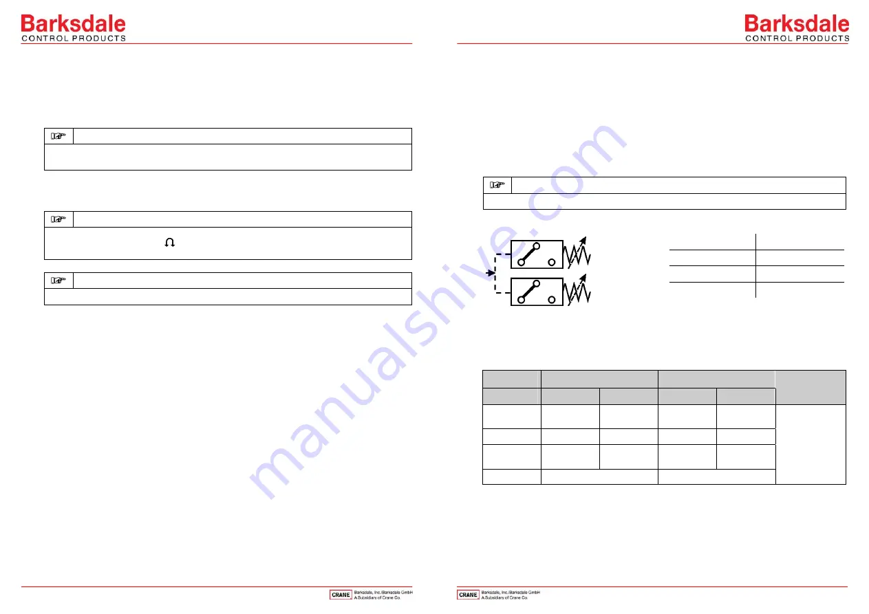
Wiring Code for all Types
(Contact status at atm. pressure)
at vacuum NC/NO vice versa
Power circuit
Power circuit
C = purple
C = brown
NC = blue
NC = orange
NO = red
NO = yellow
Fig. 5: Wiring Code
Wiring code/Option
Pressure 9681X/9692
Vacuum 9671X
Function
Circuit 1
Circuit 2
Circuit 1
Circuit 2
Option
Normally
Open/NO
red
yellow
blue
orange
Common/C
purple
brown
purple
brown
Normally
Closed/NC
blue
orange
red
yellow
Earth
green
green
K with
mounting
holes
7
6
NO
NC
c
NO
NC
c


