7
INSTALLATION
INITIAL HARDWARE SETUP
1. Remove controller from packaging. Keep all packing material until proper
operation has been verified.
2. Use the "bail" bar (or tilt-stand) at the bottom of the unit to adjust position
for easy viewing of front panel.
Caution:
To avoid electric shock, the power cord pro-
tective grounding conductor must be con-
nected to earth-ground.
Caution:
Install an independent temperature limit con-
trol protection system where a fault condition
could result in fire or other hazard. Failure to
install such a system could result in injury to
personnel or damage to property.
3.
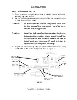
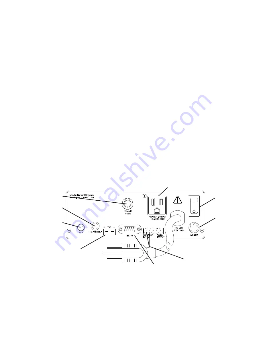
Plug the unit in to a correctly rated AC outlet and turn on the power using
the ON/OFF switch on the back panel. Refer to Figure 5.
FIGURE 5. 115 V BACK PANEL
3 Wire RTD
Probe Jack
Thermistor
Probe Jack
Heater/Cooler
Output Fuse
ON/OFF
Switch
Main
Power
Fuse
Heater Cord
Cable Connection
Recorder Output
Isolated 4-20 mA
RS-232-C Serial
Connector
Mini-ANSI Thermocouple
Jack (500 ohm Max
Load Resistance)
115 V

