8
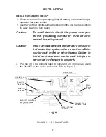
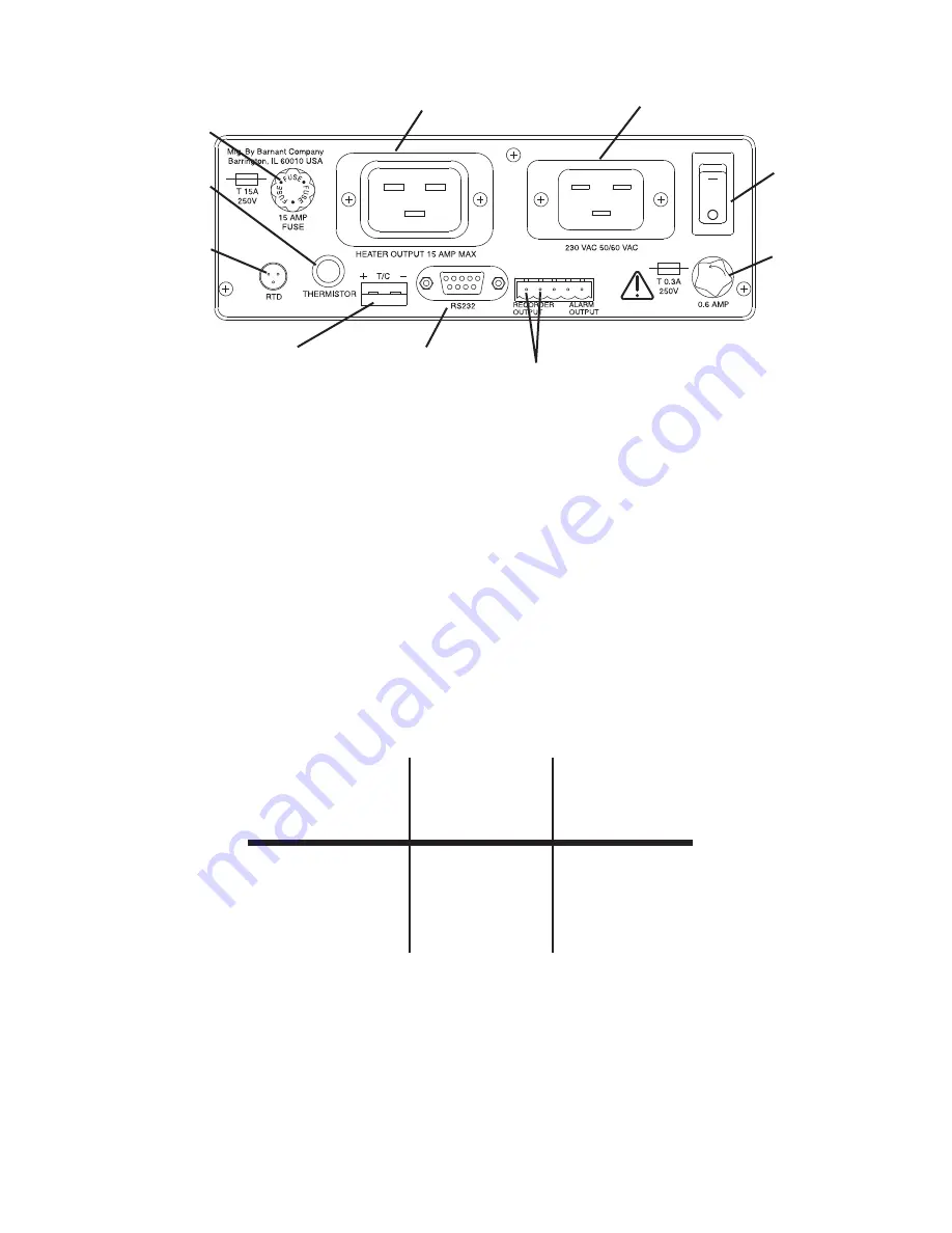
Line Cord
Connection
Heater Cord
Cable Connection
Recorder Output
Isolated 4-20 mA
RS-232C Serial
Connector
Mini-ANSI Thermocouple
Jack (500 ohm Max
Load Resistance)
Heater/Cooler
Output Fuse
Thermistor
Probe Jack
3 Wire RTD
Probe Jack
ON/OFF
Switch
Main
Power
Fuse
230 V
FIGURE 5. 230 V BACK PANEL
4.
Connect one of the three types of sensors to the unit (refer to Accesso-
ries section for a listing of compatible probes).
5.
Connect the heater or cooler (maximum of 15 A) to the unit.
6.
Install the PC (personal computer) cable to the RS-232-C serial commu-
nications terminal, if desired. Refer to your PC hardware guide for PC
connections.
7.
The following charts show the required connections for interfacing to an
IBM-compatible computer with either a 9-pin or 25-pin plug. The cables
listed in the Accessories section are properly wired for use.
Temperature
Controller
Computer
Computer
DB-9
DB-9
DB-25
Pin 2
Pin 3
Pin 2
Pin 3
Pin 2
Pin 3
Pin 5
Pin 5
Pin 7
RS-232-C Connection Chart
NOTE: The serial data format is full duplex, 1 start bit, 8 data bits, no
parity, and 1 stop bit. The baud rate is user-selected.

