27
Each CP number represents a set of proportional band, integral time, and
derivative rate values. This is included for convenience in setting ramp and
soak PID values when individual segments have different stability require-
ments. Specific CP values are set in Control Parameters, below. Selecting
CP 0 will assign the auto tune PID values to the segment.
3. Press the MENU key to advance to CP setup.
Control Parameters (CP)
1. Nine control parameter numbers are available for storing up to nine sets
of PID values. The PID values can be determined experimentally but
auto tune values can be used by selecting CP 0. Use the arrow keys to
set the P, I, and D values for that CP value.
2. Press the MENU key to advance to Cycle Time set up.
Cycle Time
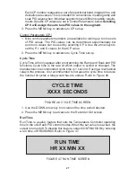
Cycle Time will only appear after programming the Ramp and Soak and PID
functions. Cycle time is the rate at which output is cycled or changed. The
manufacturer's recommended cycle time is 1 second. If using a mechanical
relay in the process, it is recommended to increase the cycle time to reduce
the number of cycles a relay would have to endure. Refer to Figure 46.
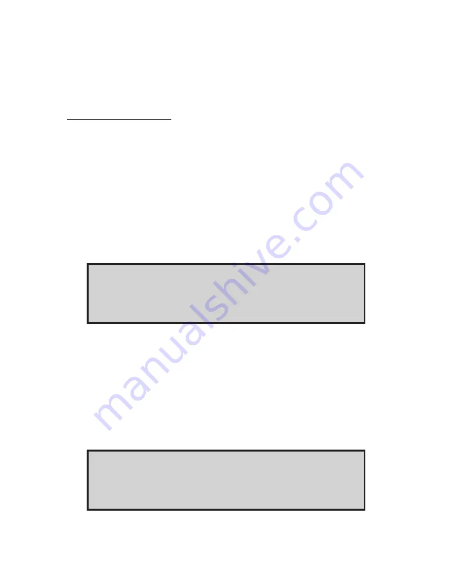
CYCLE TIME
XXXX SECONDS
FIGURE 46. CYCLE TIME SCREEN
1. Use the DOWN arrow key to increment the time period desired.
2. Press the MENU key to advance to the Recorder Out screen.
Run Time
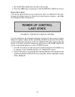
Run Time is a safety feature that sets the Temperature Controller operating
time in the on/off and PID control modes. When the set value is reached, the
output is turned off. To disable this feature, select CONTINUOUS by entering
a run time of HR00 MIN00. Refer to Figure 47.
RUN TIME
HR XX MIN XX
FIGURE 47. RUN TIME SCREEN

