background image

9

SECTION E: PREVENTATIVE MAINTENANCE

As the motor is oil fi lled, no lubrication or other maintenance 
is required, and generally CP&S pumps will give very reliable 
service and can be expected to operate for years on normal 
sewage pumping without failing. However as with any 
mechanical piece of equipment a preventive maintenance 
program is recommended and suggested to include the 
following checks:

WARNING ! - Pressure builds up due to heat.

1)  Inspect motor chamber for oil level and contamination and 
 

repair as required per section F-1.

2)  Inspect impeller and body for excessive build-up or clogging 
 

and repair as required per section F-2.

3)  Inspect motor and bearings and replace as required per
  

section F-3.

4)  Inspect seal for wear or leakage and repair as required per
 

section F-4.

SECTION F: SERVICE AND REPAIR

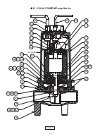
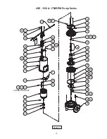
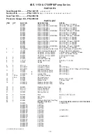
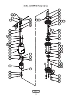
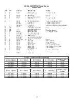
NOTE: All item numbers in ( ) refer to Figures 12, 13, 14 
& 15.

F-1) Lubrication:

Anytime the pump is removed from operation, the cooling oil 
in the motor housing (2) should be checked visually for oil 
level and contamination.

F-1.1) Checking Oil:
Motor Housing -

 To check oil, set unit upright. Remove pipe 

plug  (5)  from  motor  housing  (2).  With 

a  fl ashlight,  visually 

inspect  the  oil  in  the  motor  housing  (2)  to  make  sure  it  is 
clean and clear, light amber in color and free from suspended 
particles.  Milky  white  oil  indicates  the  presence  of  water.  Oil 
level should be just above the motor when pump is in a vertical 
position.

F-1.2) Testing Oil:

1.  Place pump on it’s side, remove pipe plug (5), from motor
 

housing (2) and drain oil into a clean, dry container.

2.  Check oil for contamination using an oil tester with a range
 

to 30 Kilovolts breakdown.

3.  If oil is found to be clean and uncontaminated (measure
 

above 15 KV. breakdown), refi ll the motor housing as per


section F-1.4.

4.  If oil is found to be dirty or contaminated (or measures
 

below 15 KV. breakdown), the the pump must be carefully


inspected for leaks at the shaft seal (46), cable assemblies


(52) and (53), square ring (42) and pipe plug (5)    


before refi lling with oil. To locate the leak, perform


a pressure test as per section F-1.3. After leak is repaired,


refi ll with new oil as per section F-1.4.

F-1.3) Pressure Test:
Pumps that have had the oil drained from the Motor 
Housing -

 Apply pipe sealant to pressure gauge assembly 

and tighten into pipe plug hole (See Figure 2).  Pressurize 
motor housing to 10 P.S.I. Use soap solution around the 
sealed areas and inspect joints for “air bubbles”. If, after 
fi ve minutes, the pressure is still holding constant, and no 
“bubbles” are observed, slowly bleed the pressure and 
remove the gauge assembly. Replace oil as described in 
section F-1.4. If the pressure does not hold, then the leak 
must be located and repaired. 

Pumps that have NOT had the oil drained from the Motor 
Housing - 

The pressure test may be done with the oil at its 

normal level.  Remove pipe plug (5) from motor housing (2). 
Apply pipe sealant to pressure gauge assembly and tighten 
into hole (see Figure 2). Pressurize motor housing to 10 P.S.I. 
Use soap solution around the sealed areas above the oil level 
and inspect joints for “air bubbles”. For sealed areas below 
the oil level, leaks will seep oil.

If, after fi ve minutes, the pressure is still holding constant, 
and no “bubbles”/oil seepage is observed, slowly bleed the 
pressure and remove the gauge assembly. If the pressure 
does not hold, then the leak must be located and repaired.

CAUTION ! - Pressure builds up extremely 
fast, increase pressure by “TAPPING” air 
nozzle. Too much pressure will damage 
seal. DO NOT exceed 10 P.S.I.

Seal Chamber -

 Set unit on its side with fi ll plug (5) 

downward, remove plug (5) and drain all oil from seal 
chamber. Apply pipe sealant to pressure gauge assembly 
and tighten into hole in bearing bracket (21). Pressurize seal 
chamber to 10 P.S.I. and check for leaks as outlined above.

F-1.4)  Replacing Oil:
Motor Housing-

 Set unit upright and refi ll with new cooling 

oil as per Table 1 (see parts list for amount). Fill to just above 
motor as an air space must remain in the top of the motor 
housing to compensate for oil expansion (see Figure 2, 12 or  
14). Apply pipe thread compound to threads of pipe plug (5) 
then assemble to motor housing (2).

IMPORTANT! - For single phase units, oil level 
should be below capacitor.

Seal Chamber -

 Set unit on its side, with plug (5) upward, 

and refi ll with new oil as per Table 1 (see parts list for 
amount). Apply pipe thread compound to threads of pipe plug 
(5) and assemble to bearing bracket (21).

FIGURE 2

Summary of Contents for 4SE-L series

Page 1: ...program product changes may occur As such Crane Pumps Systems reserves the right to change product without prior written notification 420 Third Street 83 West Drive Brampton Piqua Ohio 45356 Ontario...

Page 2: ...RPM Fig 13 17 PARTS LIST 18 20 CROSS SECTION 3450RPM Fig 14 21 EXPLODED VIEW 3450RPM Fig 15 22 PARTS LIST 23 24 WARRANTY 25 RETURNED GOODS POLICY 26 WARRANTY REGISTRATION 26 SPECIAL TOOLS AND EQUIPMEN...

Page 3: ...OT insert ngers in pump with power connected Always wear eye protection when working on pumps Make sure lifting handles are securely fastened each time before lifting DO NOT operate pump without safet...

Page 4: ...Magnet Wire Class F on selected models Service Factor 1 15 SINGLE PHASE Permanent Split Capacitor PSC Includes overload protection in motor THREE PHASE 200 230 460 60Hz is Tri voltage motor 575V Requ...

Page 5: ...Filled Squirrel Cage Induction Winding Class B Class H Rated Magnet Wire Service Factor 1 15 THREE PHASE Dual voltage 230 460 motor 575V Requires overload protection to be included in control panel VF...

Page 6: ...n or basin shall be vented in accordance with local plumbing codes This pump is designed to pump sewage effluent or other nonexplosive or noncorrosive wastewater and shall NOT be installed in location...

Page 7: ...ads for continuity resistance no moisture and the junction box control box for moisture content The above situations may induce a false signal in the moisture detecting circuit If none of the above te...

Page 8: ...0 35 9 42 7 12 4 SOOW SOW 68 17 4 7 64 1 77 4SE2844L 2 8 460 3 60 1750 G B 4 0 21 3 14 4 SOOW SOW 57 14 5 10 64 4SE2854L 2 8 575 3 60 1750 F B 3 2 14 4 14 4 SOOW SOW 57 14 5 4 68 16 63 4SE3724L 3 7 23...

Page 9: ...l as per section F 1 4 F 1 3 Pressure Test Pumps that have had the oil drained from the Motor Housing Apply pipe sealant to pressure gauge assembly and tighten into pipe plug hole See Figure 2 Pressur...

Page 10: ...n oil from motor as outlined in paragraph F 1 2 Disassemble volute and impeller as outlined in paragraph F 2 1 and disassemble shaft seal as outlined in paragraph F 4 1 Position unit upright using blo...

Page 11: ...12 using connectors 11 and wire assemblies 12 as required Do not use wire nuts Slip motor leads and ground wire through fiberglass sleeve 10 Lower motor housing 2 down onto bearing bracket 21 while al...

Page 12: ...nge seal components replace the entire shaft seal 46 F 4 2 Reassembly Diaphragm At reassembly make sure the bulge and molded in part number of diaphragm 32 is facing the seal plate 25 With diaphragm 3...

Page 13: ...aragraph F 1 4 SECTION G REPLACEMENT PARTS G 1 ORDERING REPLACEMENT PARTS When ordering replacement parts ALWAYS furnish the follow ing information 1 Pump serial number and date code Paragraph G 4 2 P...

Page 14: ...14 FIGURE 11...
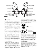
Page 15: ...security and condition Clean impeller and inlet of any obstruction 9 Loosen union slightly to allow trapped air to escape Verify that turn off level of switch is set so that the suction is always ood...

Page 16: ...16 61 60 52 53 15 3 26 34 35 19 20 24 28 9 44 43 47 30 29 58 59 2 1 46 33 56 55 54 57 10 27 18 16 14 39 25 21 42 32 48 49 OIL LEVEL 49 50 31 51 FIGURE 12 4SE 1150 1750RPM Pump Series...

Page 17: ...4 35 48 28 42 58 59 51 39 49 49 25 32 43 9 44 46 27 18 31 21 42 14 16 5 6 49 4 53 52 57 56 7 54 55 6 4 49 5 50 2 20 19 15 3 10 1 33 30 29 47 60 61 11 12 CONNECTOR ASSY 50 50 FIGURE 13 4SE 1150 1750RPM...

Page 18: ...se 4 6 026322 Lock washer 5 16 SS 5 2 014270 3 8 NPT Pipe Plug ZP 6 6 1 156 1 HXHD Cap Screw 5 16 18 x 1 LG SS 7 1 103503 Handle SS 9 4 20 13 1 1 4 Lock washer SS 10 2 625 02117 Fiberglass Sleeve 230V...

Page 19: ...D Cap Screw 1 4 20 x 1 LG SS 42 2 033730 t Square Ring Buna N 43 1 022879 Diaphragm Clamp Ring AI 44 4 002204 HXHD Cap Screw 1 4 20 x 1 LG Steel 4 1 7 1 HXHD Cap Screw 1 4 20 x 1 LG SS 46 1 064434 t S...

Page 20: ...103739XL 103586 4SE5044L 103742XC 103742XF 103742XL 103583 4SE5054L 103742XC 103742XF 103742XL 103583 MODEL NUMBER 30 FT SENSOR 50 FT SENSOR 100 FT SENSOR TERMINAL BLOCK SENSOR 4SE1926L 113288XC 1132...

Page 21: ...21 4SE L 3450RPM Pump Series FIGURE 14...

Page 22: ...2 63 26 24 34 35 28 42 58 59 51 39 25 32 43 9 44 46 27 18 21 42 14 16 5 47 29 30 33 1 12 10 11 60 61 19 20 2 5 7 4 6 57 56 55 54 53 52 4 6 49 49 50 50 31 49 49 48 49 50 FIGURE 15 4SE L 3450RPM Pump Se...

Page 23: ...105149A Jumper Wire 230V 3 Phase 13 150 oz 029034 Oil Motor Housing 40 oz 029034 Oil Seal Cavity 14 2 038156 Machine Screw 6 32 x 3 8 LG ZP 16 1 133403B Moisture Sensor Wire Red 1 133403A Moisture Sen...

Page 24: ...Cord Terminal Block 57 2 2 31051 224 O Ring Buna N 58 2 026989 Shim 005 Use as required 59 2 028120 Shim 010 Use as required 60 2 016660 Self Tap Screw 8 32 x 3 8 LG SS 61 1 105111 Ground Wire Sensor...

Page 25: ...s between the results of eld testing conducted by or for user and laboratory tests corrected for eld performance the latter shall control RECOMMENDATIONS FOR SPECIAL APPLICATIONS OR THOSE RESULTING FR...

Page 26: ...nt To Insure That Employees Will Not Be Exposed To Health Hazards In Handling Said Material All Applicable Laws And Regulations Shall Apply IMPORTANT WARRANTY REGISTRATION Your product is covered by t...

Reviews: