background image

41

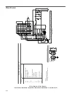
  Wiring Diagram Wiring Diagram

             F46230CM-33, F46240CM-33, F46240CM-33-75

SERIES ELEMENTS

CONTROLLER

SUPPLIED WITH CURRENT CONTROLLER.

FUSE AND FUSE HOLDER ARE

NOTES:

HEATING ELEMENT

INDICATOR LAMP

HR1 to

HR8

DS1

3

7

O

B

17

13

INTERNAL COMMUNICATION CABLE WIRING

CONNECTOR

2

1

R

W

15

2

EMI LINE FILTER

CONTROLLER, TEMPERATURE

CONTROLLER, CURRENT

CIRCUIT BREAKER

CONTACTOR, MECHANICAL

PART NO.       DESCRIPTION

DIAGRAM COMPONENT LIST

FAN

FAN

TRANSFORMER

THERMOCOUPLE

T1

TC1

K1

B2 & 3

B1

CB1

CN1

CN2

C

C

HR6

HR1

HR2

240 VOLTS

208 VOLTS

T1

HR3

HR4

6

HR5

CN2

3

5

4

2

1

HR7

GND

HR8

L1

DS1

B1

B3

B2

L2

FUSE

K1

16

25

27

26

9

8

7

18

17

-

6

5

14

4

3

2

13

12

11

+

33

32

31

30

29

1

10

CN1

28

CB1

RED

TC1

BLACK

GND

SW1

SW1

DOOR SWITCH

W

IRING

 D

IAGRAM

Summary of Contents for F46110CM

Page 1: ...matic F46110CM 33 F46230CM 33 Automatic F46118CM F46238CM Automatic F46120CM F46240CM Multi Programmable F46120CM 33 F46240CM 33 Multi Programmable F46128CM F46248CM Multi Programmable F46120CM 75 F46...

Page 2: ...nace 14 Power Switch 14 Cycle Indicator 14 Circuit Breaker 15 Fans 15 Controllers 15 Operation of Automatic Models 16 Control Parameters 16 Tuning Your Furnace 17 Single Set Point Operation 18 Program...

Page 3: ...General Cleaning Instructions 32 Problem Solving Guide 33 Maintenance and Servicing 34 Wiring Diagram 38 Wiring Diagram 39 Wiring Diagram 40 Wiring Diagram 41 Replacement Parts List 42 Ordering Proce...

Page 4: ...urnace than for lower temperature laboratory furnaces For maximum safety and longest furnace life be sure to observe the various cautions and warnings throughout this manual Alert Boxes WARNING Warnin...

Page 5: ...r clean furnace without proper eye protection 3 Do not use in the presence of flammable or combus tible materials fire or explosion may result This device contains components which may ignite such mat...

Page 6: ...the door the hearth collar in the chamber of the product or under the hot plate top Tests performed by the manufacturer indicate that there is no risk of exposure to dust or respi rable fibers resulti...

Page 7: ...ause of the stresses caused by extremely high temperature opera tion these blocks will show some surface cracking This cracking is not detrimental to the operation of the fur nace A precious metal typ...

Page 8: ...of the controller The circuit breaker is used to turn the furnace on and off and also protects the electrical supply in the event that the furnace draws too much electrical current The pilot light in...

Page 9: ...2 40 10 4 40 12 Watts 9600 8320 9600 8320 9600 8320 2500 2500 2500 2500 2500 2500 Phase 1 1 1 1 1 1 Temp Range Cont 1700 C 1700 C 1700 C 1700 C 1700 C 1700 C Controller Automatic Automatic 4 Program 4...

Page 10: ...1700 C 1700 C 1700 C 1700 C 1700 C Controller Automatic Automatic 4 Program 4 Program Multi Prog Multi Prog Power and current required to maintain maximum temperature after stabilization The maximum c...

Page 11: ...t for the heating of materials per the provisions of the Electromagnetic Compatability Directive 89 336 EEC as amended by 92 31 EEC and 93 68 EEC and per the provisions of the Low Voltage Directive 73...

Page 12: ...ON Be sure ambient temperature does not exceed 104 F 40 C Ambient temperatures above 104 F 40 C may result in damage to the controller Allow at least six inches 15 cm of space between the furnace on a...

Page 13: ...e 208 or 240 volt service to the bottom terminal L2 and the ground usually green wire to the center terminal marked GND For 220 volt service connect the neutral to the top terminal marked L1 the 220 v...

Page 14: ...ntact 6 To AVOID EYE DAMAGE in operating or cleaning furnace proper eye protection must be worn 7 To AVOID BURNS do not stand directly in front of the chamber without wearing a heat resistant faceshie...

Page 15: ...to alternate between set point SP and output power OP To enter the main scroll list list of all controller param eters that are accessed through front keyboard the scroll button should be held depres...

Page 16: ...function Self tuning automatically determines this setting AL1 Alarm 1 is a full scale alarm which protects load and furnace when temperature exceeds preset value Furnace will control temperature at t...

Page 17: ...be changed use temperature set point that your application requires At the end of one minute the SP indicator will stop flashing indicating that the set point can no longer be changed The A T indicato...

Page 18: ...temperature To operate the control 1 Turn power switch to the ON position The set point temperature presently set in the control will appear on the lower display 2 To change this set point depress th...

Page 19: ...will indicate RAMP While a program is running the short scroll will contain three parameters SP set point OP output power Time time remaining in program ramp to reach set point temperature Single dep...

Page 20: ...repeated Push up or down button to set SP1 setpoint one which indicates current setpoint Push up or down button to set SP2 Setpoint two Not configured into control and nonfunctional Set to 20 Operatio...

Page 21: ...nace The next five parameters proportional PB integral i derivative d cutback low cbl and cutback high cbh are for high accuracy control These values cannot be changed by the user the controller autom...

Page 22: ...tem perature you intend to use for your application If you will be running a multi step program set the furnace s setpoint to the value of PL1 Program Level 1 At the end of one minute the SP indicato...

Page 23: ...or down buttons to choose a setpoint temperature To operate the control as a single set point control 1 Turn front circuit breaker switch to the ON position The setpoint temperature presently set in...

Page 24: ...to select a program number from 1 to 15 On the F46120CM F46120CM 33 F46128CM F46240CM F46240CM 33 and F46248CM models this is selected between 1 4 To link programs together Push scroll button until C...

Page 25: ...is displayed By pressing either the up or down button the present value of this level is indicated in display units Using the up or down button will scroll the present value to the new value required...

Page 26: ...value away from the current setpoint either above or below before the program is forced into hold The program will remain in hold until the measured value comes within holdback limits This feature is...

Page 27: ...s running If it is necessary to alter a parameter while a program is running the pro gram must be placed into the hold condition To put program into hold push run hold button once After modification o...

Page 28: ...sh the HOLD legend Program Reset A running held or finished program can be reset by de pressing the up and down push buttons together When the reset has been enabled the parts of the display associate...

Page 29: ...mproper loading Because of the possibility of erosion of the insulation on the floor of the furnace chamber a separate hearth plate should be used when possible In general space should be left on all...

Page 30: ...helium atmospheres to 1600 C Reducing atmospheres are not recommended The heating elements in this furnace are attacked by fluorine chlorine sodium and potassium compounds and also by molten metals Th...

Page 31: ...nufacturer indicate that there is no risk of exposure to dust or respi rable fibers resulting from operation of this product under normal conditions However there may be a risk of exposure to respirab...

Page 32: ...tal to operation 2 Clean exterior surfaces with lightly dampened cloth containing mild soap solution 3 Occasionally check the electrical connections in the control section Repeated heating and cooling...

Page 33: ...Do not continuously below 800 C operate below 800 C Contact Barnstead Thermolyne Heating element contamination OR displayed Open thermocouple Replace thermocouple Slow heat up Operating 240V furnace I...

Page 34: ...of the product or under the hot plate top Tests performed by the manufacturer indicate that there is no risk of exposure to dust or respi rable fibers resulting from operation of this product under no...

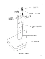
Page 35: ...n the insulation Save the blanket insulation for reuse d Remove the element ceramic holder noting its exact position on the heating element e Fasten the element ceramic holder on the new ele ment in e...

Page 36: ...ouple a Remove top cover from the heating chamber side of furnace b Loosen diagonal screw holding ceramic connection block c Lift connection block d Loosen connection block screws holding thermocouple...

Page 37: ...37 Figure 1A Element Replacement...

Page 38: ...COMMUNICATION CABLE WIRING CONNECTOR 2 1 R W 15 2 CONTROLLER TEMPERATURE CONTROLLER CURRENT CIRCUIT BREAKER CONTACTOR MECHANICAL TRANSFORMER THERMOCOUPLE PART NO DESCRIPTION DIAGRAM COMPONENT LIST CN2...

Page 39: ...ANICAL TRANSFORMER THERMOCOUPLE INDICATOR LAMP HEATING ELEMENT 208 VOLTS 240 VOLTS 1 10 28 2 11 29 3 12 30 4 13 31 5 14 32 6 33 7 16 8 17 26 9 18 27 BLACK RED GND GND L1 L2 1 2 3 4 5 6 T1 K1 CN2 HR1 H...

Page 40: ...ECHANICAL TRANSFORMER THERMOCOUPLE INDICATOR LAMP HEATING ELEMENT 208 VOLTS 240 VOLTS 1 10 28 2 11 29 3 12 30 4 13 31 5 14 32 6 33 7 16 8 17 26 9 18 27 BLACK RED GND L1 L2 1 2 3 4 5 6 T1 K1 CN2 HR1 HR...

Page 41: ...CONNECTOR 2 1 R W 15 2 EMI LINE FILTER CONTROLLER TEMPERATURE CONTROLLER CURRENT CIRCUIT BREAKER CONTACTOR MECHANICAL PART NO DESCRIPTION DIAGRAM COMPONENT LIST FAN FAN TRANSFORMER THERMOCOUPLE T1 TC1...

Page 42: ...req d Fuse Thyristor Fast Blow 250V 45 Amp FZX42 FZX42 Fuse Holder FZX62 FZX62 Hearth Plate PH461X1 PH462X1 Injection Port w plug JC633x1 JC633x1 JC633X2 plug JC633X2 plug Insulation door JN461X3 JN4...

Page 43: ...er from whom you purchased this unit or can be obtained promptly from the factory When service or replacement parts are needed we ask that you check first with your dealer If the dealer cannot handle...

Page 44: ...er Solubility NIL Melting Point 3000 F Vapor Density Air l NA Volatile by Volume 0 FIRE AND EXPLOSION DATA Flash Point Method NONFLAMMABLE NFPA Flammable Combustible Liquid Classification NAFlammable...

Page 45: ...IVITY DATA MATERIAL IS STABLE HAZARDOUS POLYMERIZATION CANNOT OCCUR Chemical Incompatibilities HYDROFLUORIC ACID Conditions to Avoid NONE IN DESIGNED USE Hazardous Decomposition Products NONE SPILL OR...

Page 46: ...Y ASPECTS OF REFRACTORY CERAMIC FIBERS IS AVAILABLE Copyright 1980 National Fire Protection Assoc Quincy MA 02269 This reprinted material is not the complete and official position of the NFPA on the r...

Page 47: ...on must be returned to our factory and if upon inspection it is concluded that failure is not due to ex cessive high temperature or contamination warranty replacement will be provided by Barnstead The...

Page 48: ...arnstead Thermolyne 2555 Kerper Blvd P O Box 797 Dubuque IA 52004 0797 USA PHONE 319 556 2241 800 553 0039 FAX 319 556 0695 Web Address http www barnsteadthermolyne com a subsidiary of 9001 ISO REGIST...

Reviews: