Power Switch
Controls power to the furnace. Switch to the “ON” position
to energize the elements and the controller.
Cycle Indicator (OP1)
The amber cycle light will illuminate when electricity is
being supplied to the elements.
Circuit Breaker
A double pole circuit breaker is located at the bottom of
the control section. It serves to turn electricity ON and
OFF and to protect the electrical circuit.
Fans
The fans, located in the rear of the heating section and
the control section, will run continuously as long as elec-
tricity is supplied to the furnace, even when the furnace
panel circuit breaker is OFF. This serves to remove resid-
ual heat after the furnace is turned OFF so the heat does
not cause damage to the controls.
Controllers
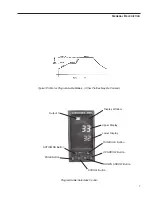
Your furnace’s controller consists of a microprocessor
based three-mode (Proportional, Integral, Derivative), pro-
grammable control with over temperature protection and
appropriate output switching devices to control the fur-
nace. The digital readout continuously displays chamber
(upper display) and setpoint (lower display) temperatures
unless the SCROLL button or PAGE button is depressed.
14
G
ENERAL
O
PERATION OF
F
URNACE
Caution
Remember that when the power
switch is “ON,” the furnace will begin
to heat to the setpoint temperature that
was previously set in the controller.
Caution
If the electrical supply must be discon-
nected from the furnace at any time,
be sure the chamber temperature is
500°C or less before doing so.
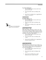
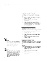
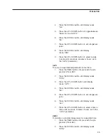
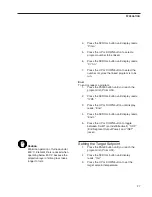
Note
When performing operations on the
controller, remember that if you
depress and release either the PAGE,
SCROLL, UP or DOWN buttons and
more than 8 seconds elapse before
the buttons are used again, the dis-
play screen will automatically switch
back to displaying setpoint tempera-
ture. If this happens, you will have to
step through each parameter until
you reach the point at which the inter-
ruption occurred. The parameter val-
ues you adjusted earlier, however, will
not be lost or altered.


