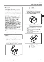
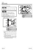
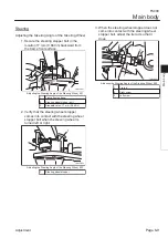
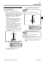
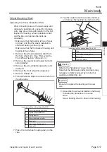

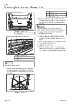
Installing the Steering Wheel Section
Caution
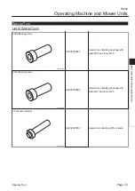
Refer to the Tightening Torque Table.
Note that the Baroness product warranty may
not apply to defects caused by incorrect or
overtorque tightening, etc.
Important
Be sure to replace the U nut with a new one.
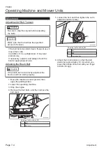
Secure the two bolts on the left and right of
the front side of the axle installation bracket
using nut A. Tighten until the axle
installation bracket moves lightly.
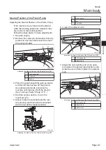
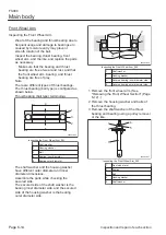
Attach the tilt lever.
Attach a washer, disc spring washer and tilt
lever, in that order, to the frame with the tilt
lever bolt.
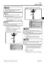
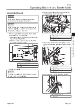
Secure the tilt lever bolt with bolts with
hexagonal hole and nuts B so that the tilt
lever will be in the Lock position on the
control panel when the axle installation
bracket fixed.
1
2 3
5
7
6
6
7
4
8
9
10
2
3
s6l7xh-001
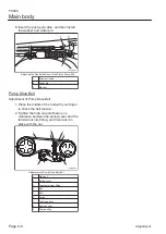
Installing the Steering Wheel Section_001
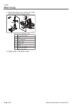
1
Axle installation bracket
2
Bolt
3
Washer
4
Nut A
5
Tilt lever bolt
6
Bolt with hexagon hole
7
Nut B
8
Tilt lever
9
Disc spring washer
10
Washer
1.
2.
3.
Main body
FS900
Main body
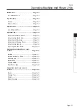
Page 6-11
Removal and installation of each section
Summary of Contents for FS900
Page 1: ...Riding Sweeper Service Manual Serial No FS900 10001 Ver 1 0...
Page 4: ...FS900 Contents...
Page 10: ...FS900 Safety Page 1 6 Safety Signs and Instruction Signs...
Page 11: ...Waste Disposal Page 2 2 About the Waste disposal Page 2 2 Disposal FS900 Disposal Page 2 1...
Page 28: ...FS900 Maintenance standards and maintenance Page 3 16 Greasing...
Page 74: ...FS900 Hydraulic system Page 4 46 Inspection and repair of each section...
Page 98: ...FS900 Electrical system Page 5 24 General inspection and repair...
Page 118: ...FS900 Main body Page 6 20 Inspection and repair of each section...


