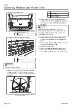
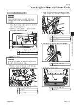
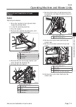
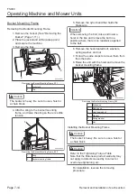
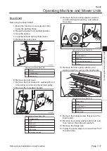
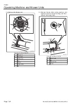
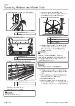
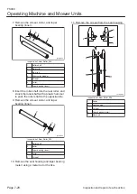
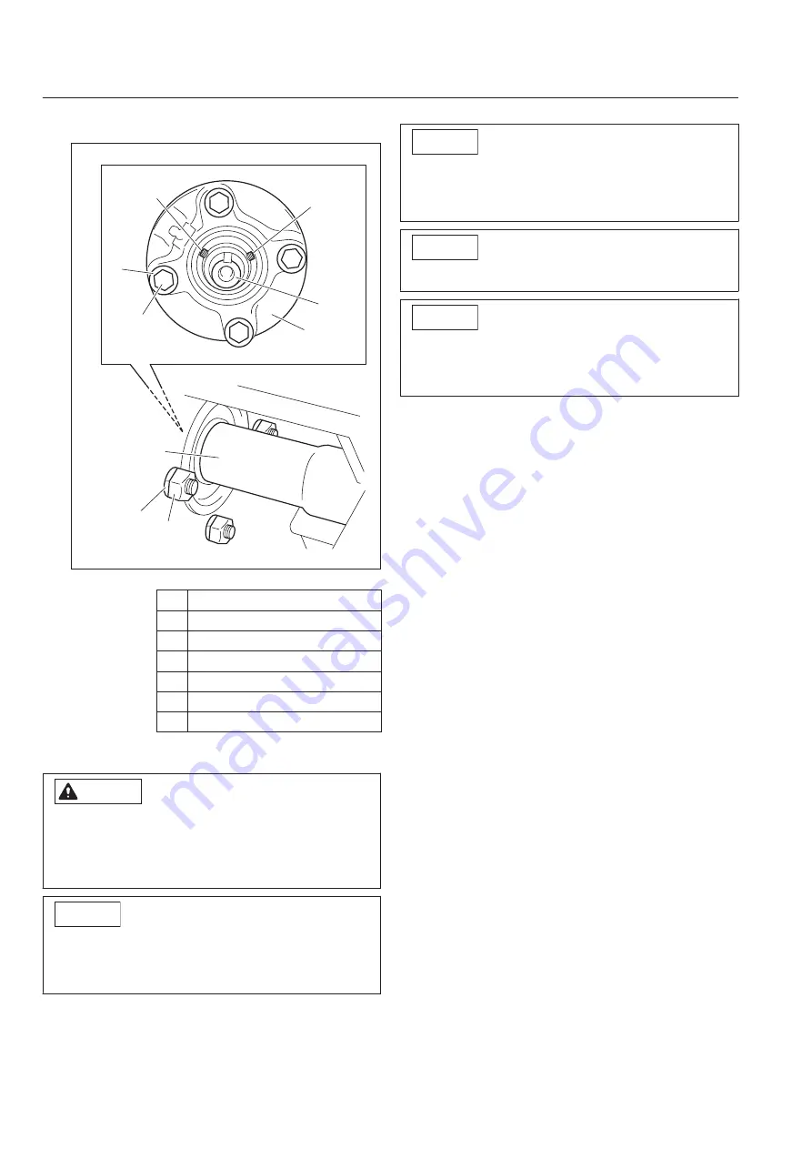
Remove the brush shaft.
2
1
2
4
5
3
3
6
7
zhswjf-005
Removing the Brush Shaft_005
1
Flange unit
2
Brush shaft
3
Hollow screw
4
Bolt
5
Washer
6
Spring washer
7
Nut
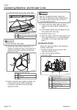
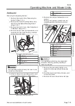
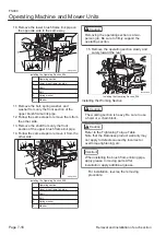
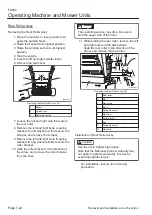
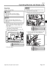
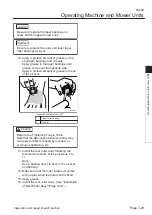
Installing the Brush Shaft
Caution
Refer to the Tightening Torque Table.
Note that the Baroness product warranty may
not apply to defects caused by incorrect or
overtorque tightening, etc.
Important
The brush shaft has a specific installation
direction.
Verify the direction before installation.
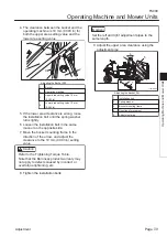
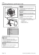
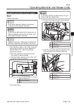
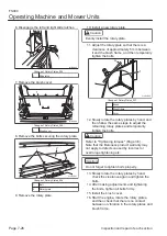
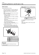
15.
Important
When installing the brush shaft, apply grease
to the input area. After installation, apply
additional grease.
Important
Apply a locking agent to the hollow screws.
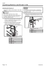
Important
The flange unit has a specific installation
direction.
Verify the direction before installation.
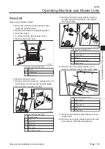
For installation, reverse the removing
procedure.
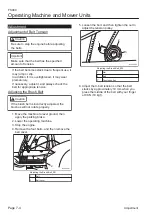
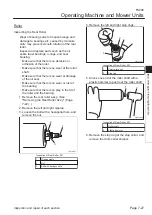
Adjust the brush.
Adjust the brush belt.
1.
2.
3.
FS900
Operating Machine and Mower Units
Page 7-18
Removal and installation of each section
Summary of Contents for FS900
Page 1: ...Riding Sweeper Service Manual Serial No FS900 10001 Ver 1 0...
Page 4: ...FS900 Contents...
Page 10: ...FS900 Safety Page 1 6 Safety Signs and Instruction Signs...
Page 11: ...Waste Disposal Page 2 2 About the Waste disposal Page 2 2 Disposal FS900 Disposal Page 2 1...
Page 28: ...FS900 Maintenance standards and maintenance Page 3 16 Greasing...
Page 74: ...FS900 Hydraulic system Page 4 46 Inspection and repair of each section...
Page 98: ...FS900 Electrical system Page 5 24 General inspection and repair...
Page 118: ...FS900 Main body Page 6 20 Inspection and repair of each section...


