
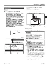
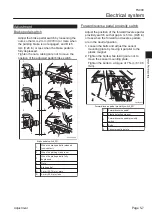
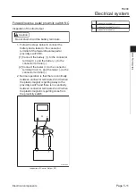
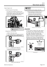
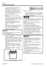
Inspection of Output Voltage
Caution
Do not short-circuit the battery terminals.
Follow the steps below to connect the
battery and a voltmeter to the connector
terminal of the forward/reverse pedal
proximity switch NC.
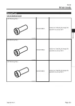
Connect the battery (+) to the connector
terminal (+), and the battery (-) to the
connector terminal (-).
Connect the voltmeter (+) to the
connector terminal Vout (+), and the
voltmeter (-) to the connector terminal (-).
It is normal that the voltage between
connector terminals 2 and 3 is the battery
voltage (12 V) when the plastic magnet is
getting away to the proximity switch, and
that voltage drops to (0 V) when the plastic
magnet is getting close from the proximity
switch.
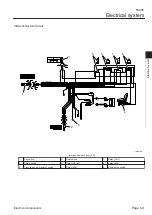
V
-
+
-
+
1
2
3
35efyq-003
Inspection of Output Voltage_001
1
Connector terminal (+)
2
Connector terminal Vout (+)
3
Connector terminal (-)
1.
[1]
[2]
2.
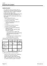
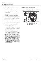
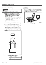
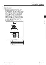
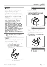
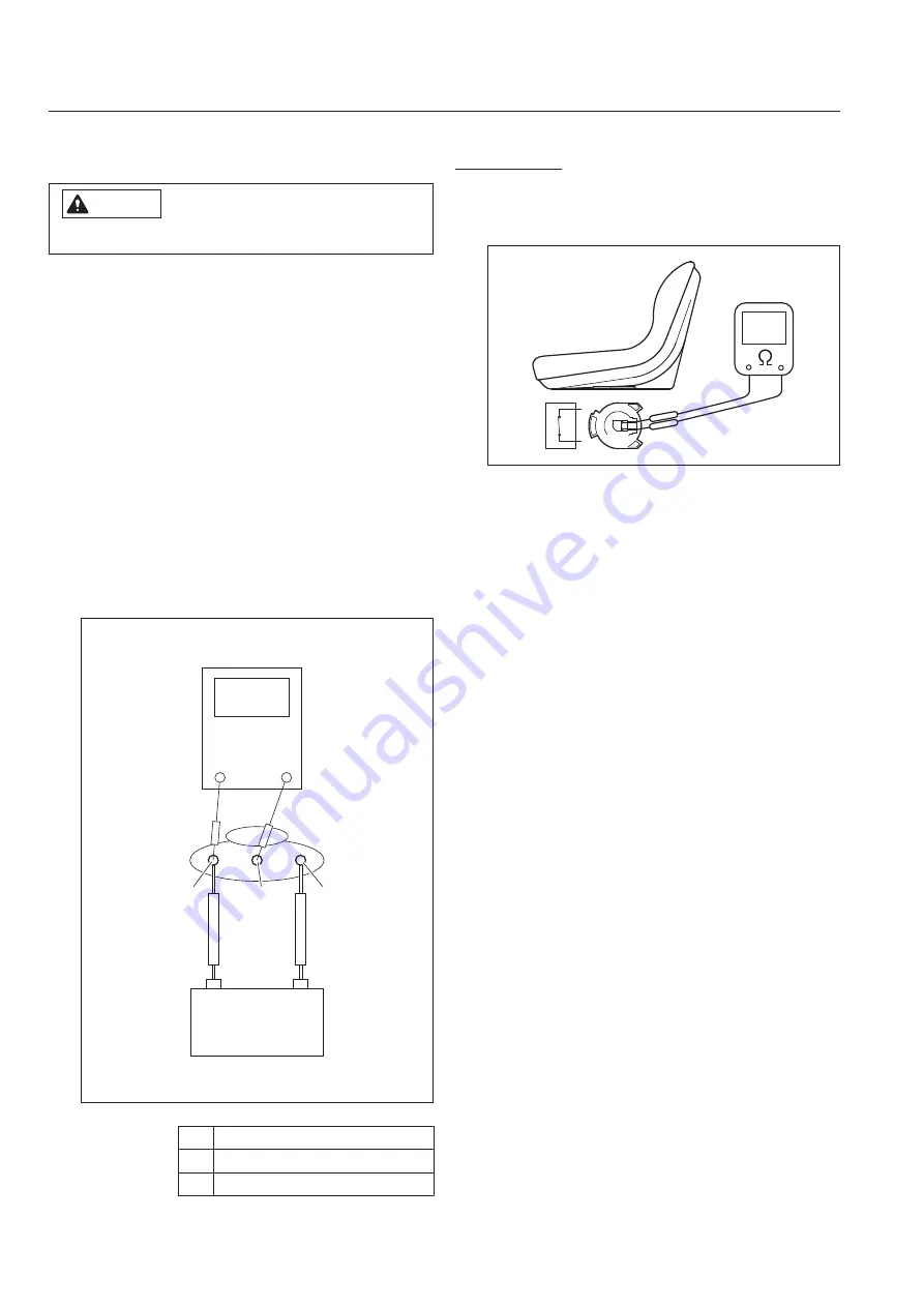
Seat Switch
The seat switch is located right underneath the
seat and is usually conducted. It is normal if its
condition is stopped when seated.
NC
6m8tje-004
Seat Switch_001
FS900
Electrical system
Page 5-12
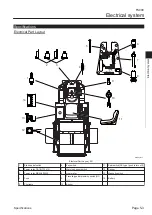
Electrical components
Summary of Contents for FS900
Page 1: ...Riding Sweeper Service Manual Serial No FS900 10001 Ver 1 0...
Page 4: ...FS900 Contents...
Page 10: ...FS900 Safety Page 1 6 Safety Signs and Instruction Signs...
Page 11: ...Waste Disposal Page 2 2 About the Waste disposal Page 2 2 Disposal FS900 Disposal Page 2 1...
Page 28: ...FS900 Maintenance standards and maintenance Page 3 16 Greasing...
Page 74: ...FS900 Hydraulic system Page 4 46 Inspection and repair of each section...
Page 98: ...FS900 Electrical system Page 5 24 General inspection and repair...
Page 118: ...FS900 Main body Page 6 20 Inspection and repair of each section...


