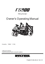
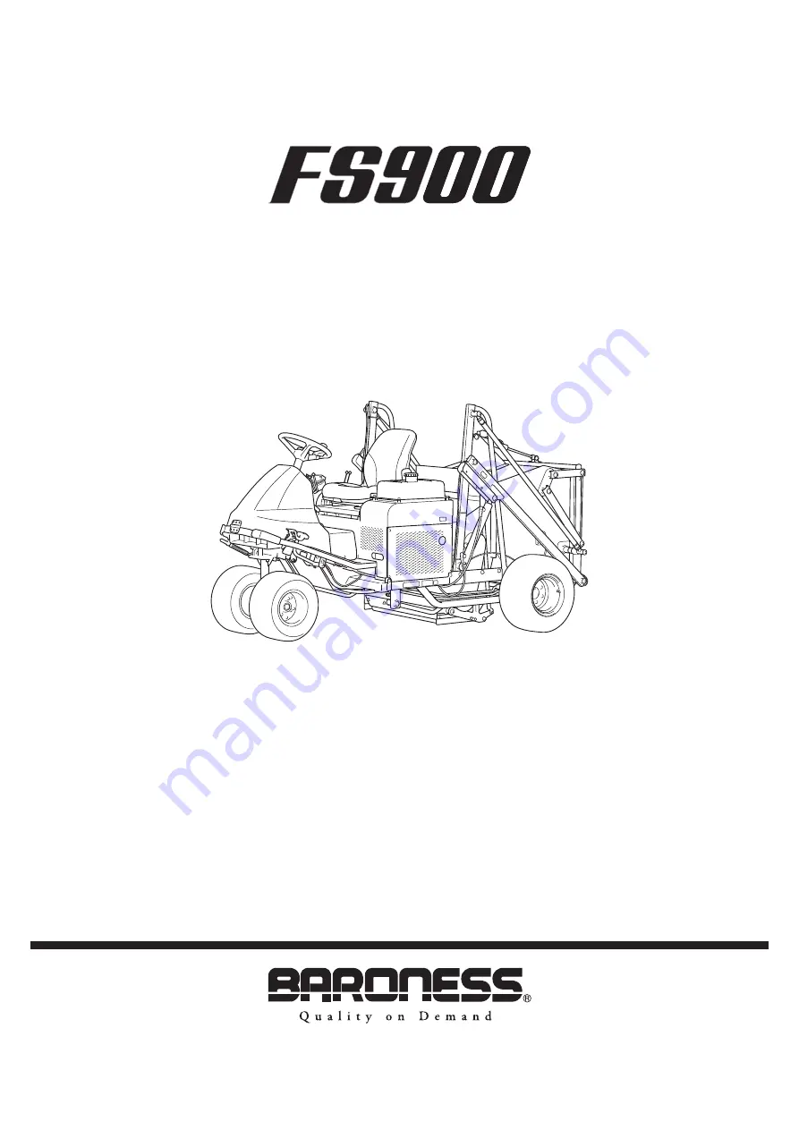
background image

Riding Sweeper

Owner's Operating Manual

Serial No. FS900

11159-

"Required reading"
Read this manual before using the machine.

Original Instructions Ver.2.5

Summary of Contents for FS900

Page 1: ...Riding Sweeper Owner s Operating Manual Serial No FS900 11159 Required reading Read this manual before using the machine Original Instructions Ver 2 5...

Page 2: ...Keep this Owner s Operating Manual in the box behind the seat 1 DC1C59A4 Keeping The Owner s Operating Manual_001 1 Box QR Code A QR code label is affixed on the machine 1 74B4C9E7 QR Code_001 1 QR co...

Page 3: ...Co Ltd Warning Symbols This manual uses the following warning symbols for handling precautions that are important for your safety 696cq5 001 Warning symbol This symbol indicates the articles regardin...

Page 4: ...nuals to thoroughly understand the contents for safe and correct operation Baroness Owner s Operating Manual The Engine s Owner s Manual The Battery s Owner s Manual Purpose This product is intended f...

Page 5: ...age 4 6 Instruments on the Operation Panel Page 4 7 Angle Meter Page 4 8 Safety Mechanisms Page 4 8 Warning Mechanisms Page 4 8 Handling Instructions Page 5 1 Operations Before Service Page 5 2 Inspec...

Page 6: ...FS900 Contents...

Page 7: ...Safe Operating Practices Page 1 2 Training Page 1 2 Preparation Page 1 2 Operation Page 1 3 Maintenance Page 1 4 Storage Page 1 4 Safety FS900 Safety Page 1 1...

Page 8: ...tching and load distribution 1 2 3 1 2 Never allow children or people unfamiliar with these instructions to use or service the machine Local regulations may restrict the age of the operator The owner...

Page 9: ...ook behind and down before backing up to be sure of a clear path 4 5 6 7 8 1 2 3 4 5 6 7 8 9 10 11 12 Slow down and use caution when making turns and crossing roads and sidewalks Use care when approac...

Page 10: ...6 7 Keep hands and feet away from moving parts If possible do not make adjustments with the engine running Make sure that parts such as wires are not touching each other and that their covers have not...

Page 11: ...inside a building where fumes may reach an open flame or spark If the engine is provided with a shut off valve shut off valve while storing or transporting Do not store fuel near flames 4 5 6 Safety...

Page 12: ...FS900 Safety Page 1 6 Safe Operating Practices...

Page 13: ...Recycle and Waste Disposal Page 2 2 About Recycle Page 2 2 About Waste Disposal Page 2 2 Disposal FS900 Disposal Page 2 1...

Page 14: ...economical use of resources It may be required by local laws About Waste Disposal Make sure that waste generated when servicing or repairing the machine is disposed of in accordance with local regula...

Page 15: ...egulation Decals Page 3 4 Description of Regulation Decals Page 3 5 Safety Signs and Instruction Signs Page 3 6 About Safety Signs and Instruction Signs Page 3 6 Positions of Safety Decals and Instruc...

Page 16: ...0 g kW h rated output 228 g PS h rated output Engine oil capacity 1 6 dm3 1 6 L 0 42 U S gal Coolant volume Hydraulic tank capacity 17 0 dm3 17 0 L 4 49 U S gal Transmission oil capacity Operating wid...

Page 17: ...l Hand Arm Vibration This machine was confirmed not to exceed a vibration level of 2 5 m s2 to hands and arms by measuring identical machines in accordance with the procedure specified in ISO 5395 1 2...

Page 18: ...inder lock 9 Brush adjusting lever 10 Brake pedal 11 Throttle lever 12 Seat 13 Brush frame 14 Bucket 15 Angle Meter 16 Outrigger 17 Stop valve Regulation Decals Positions of Regulation Decals F G A E...

Page 19: ...For UK UKCA mark indicates that the machine sold in the UK complies with the UK requirements kj8jic 003 UKCA Mark_001 Noise Emission Decal For Europe The noise emission decal indicates the sound powe...

Page 20: ...Safety Signs and Instruction Signs Important Safety decals and instruction decals are attached to this product Make sure that they are preserved in their entirety If they are damaged become dirty or p...

Page 21: ...nstruction Decals Operation Decal FS900 0512Z0 Decal operation Warning Read the Owner s Operating Manual Warning Apply the parking brake stop the engine remove the ignition key and then leave the mach...

Page 22: ...injured Warning Caution for exhaust gas Caution When the seat is raised be sure to lock the raised seat Warning Falling down Do not raise the bucket on a slope Warning Do not raise the bucket near ob...

Page 23: ...ution for High Temperatures Decal K4205001920 Decal caution for high temperatures Caution High temperature Do not touch Otherwise you will get burned xekv4l 001 Caution for High Temperatures Decal_001...

Page 24: ...NING FALLING DOWN Warning Do not raise the bucket on soft ground an uneven surface or a slope Otherwise the main vehicle will become unbalanced and fall down WARNING Do not raise the bucket on soft gr...

Page 25: ...of Operation Decals_003 13 12 8zq6pd 058 Positions of Operation Decals_004 14 A0921C55 Positions of Operation Decals_005 1 Key switch mark 2 Engine rotation mark 3 Parking brake mark 4 Tilt steering m...

Page 26: ...engine rotation 2 1 kp2t9l 011 Engine Rotation Mark_001 1 Low speed 2 High speed Parking Brake Mark Parking brake mark This indicates lock release of the parking brake 1 2 kgtxi7 004 Parking Brake Ma...

Page 27: ...f the brush 1 2 DOWN UP 8kzlbt 010 Brush Up Down Mark_001 1 DOWN 2 UP Brush Rotation Mark Brush rotation mark This indicates rotation stop of the brush 1 2 ON OFF 6ntnq3 009 Brush Rotation Mark_001 1...

Page 28: ...functions 1 2 PRESS FREE xwblkt 001 Roller Press Mark_001 1 Free 2 Press BRAKE Decal K4203001450 Decal BRAKE This indicates brake BRAKE 7elqr2 001 BRAKE Decal_001 FORWARD Decal K4203001430 Decal FORW...

Page 29: ...on Decal K4203001290 Stop valve operation decal It illustrates Stop Open of the stop valve 1 2 55wqhi 002 Stop Valve Operation Decal_001 1 Stop 2 Open Product Overview FS900 Product Overview Page 3 15...

Page 30: ...FS900 Product Overview Page 3 16 Operation Decals...

Page 31: ...op Valve Page 4 4 Bucket Up Down Lever Page 4 4 Bucket Open Close Lever Page 4 5 Roller Press Lever Page 4 6 Outrigger Page 4 6 Instruments on the Operation Panel Page 4 7 Hour Meter Page 4 8 Angle Me...

Page 32: ...area To stop the machine depress the brake pedal all the way firmly When parking depress the locking pedal while firmly depressing the brake pedal to lock it To release the brake pedal firmly depress...

Page 33: ...bucket buzzer does not sound if the bucket buzzer switch set to the OFF side 1 FREE BUCKET BUZZER ON OFF HOUR METER BUCKET FULL LOCK A B 6B2BB59B Bucket Buzzer Switch_001 1 Bucket buzzer switch A ON B...

Page 34: ...Lever Warning Do not raise the bucket on soft ground an uneven surface or a slope Otherwise the main vehicle will become unbalanced and fall down Warning Before raising the bucket stop the machine wit...

Page 35: ...own lever A Down Bucket Open Close Lever The bucket open close lever is located to the right of the driver s seat and is used when dumping collected material from the bucket When the bucket open close...

Page 36: ...If the roller press lever is shifted to the PRESS position pressure is applied to the brush frame 1 B A B A npsw8e 001 Roller Press Lever_001 1 Roller press lever A Free B Press 2 Outrigger The outri...

Page 37: ...stalled storing the machine without the tires lifted off the ground will result in the tires becoming deformed Place the jacks beneath the right rear frame area and the left rear frame area and then l...

Page 38: ...eutral position In the event the operator leaves the seat with the engine running the safety device will be activated and will stop the engine under any of the following conditions The operator leaves...

Page 39: ...achine may fall down when the bucket raised When the collected amount reaches the defined amount the bucket FULL lamp is turned on When the bucket FULL lamp is turned on immediately discharge the coll...

Page 40: ...FS900 Description of Functions Page 4 10 Warning Mechanisms...

Page 41: ...y Device Page 5 11 Around The Engine Page 5 12 Engine Oil Page 5 12 Fuel Page 5 13 Fuel Filter Page 5 14 Fuel Strainer Page 5 14 Liquid Leakage Page 5 14 Bolts and Nuts Page 5 15 Adjustment before Wor...

Page 42: ...erseat Cover_002 1 Underseat cover 2 Underseat cover stay A Lock B Release Release locking by the underseat cover stay and then close the underseat cover slowly 1 2 3 Opening and Closing of Front Cove...

Page 43: ...nearby Otherwise injuries may result Caution Sit on the seat when raising or lowering the bucket Procedure for raising the bucket Apply the parking brake on a level place 1 1 Stop the engine Importan...

Page 44: ...ggers to the position For traveling and collecting Removing and Installing The Brush Cover Procedure for removing the brush cover Move the machine to level ground Apply the parking brake Raise the buc...

Page 45: ...due to high loads Be sure to wash with water Be sure to clean the the sweeper section after work Raise the bucket 1 2 1 2 1 2 3 4 1 Stop the engine Secure the bucket position with the cylinder lock Re...

Page 46: ...ng in injuries Make sure that there is no wear or deterioration of protective covers Make sure that there is no damage to protective covers Make sure that there is no interference with moving parts du...

Page 47: ...pply oil Open the tank cap and then supply hydraulic oil through the oil filling port until the oil level reaches the middle of the oil gauge on the hydraulic tank 1 2 3 1 Tighten the tank cap securel...

Page 48: ...ic hoses and pipes Check underneath the machine for hydraulic oil leakage Air Cleaner Inspection of Air Cleaner Open the underseat cover Make sure that there is no damage to the air cleaner Make sure...

Page 49: ...battery case and that there is no electrolyte leaking If abnormalities are found immediately replace the battery 5 6 7 8 9 10 1 Cleaning the exterior Use a wet cloth for cleaning Inspect the vent plu...

Page 50: ...contact with the battery fluid or accidentally swallow the fluid Should your skin or clothes come into contact with the battery fluid immediately wash them away with water 5 Danger Danger When you sup...

Page 51: ...the braking is sufficiently effective 1 2 3 4 1 2 1 2 3 Inspection of Parking Brake Depress the locking pedal while firmly depressing the brake pedal to lock it and check that the brake is applied ef...

Page 52: ...ble materials that may be attached on or around the muffler Engine Oil Inspection of Engine Oil Important Securely tighten the oil level gauge and oil filler cap Open the underseat cover Stop the engi...

Page 53: ...l gauge 2 Oil filler cap It will take a while for the supplied engine oil to descend into the oil pan Check the oil level again 10 to 20 minutes after supplying the oil Close the underseat cover 1 2 3...

Page 54: ...fuel strainer becomes clogged with dust and dirt the fuel flow will become insufficient Periodically clean it Important Shut off the fuel valve and then clean the fuel strainer in a clean location fre...

Page 55: ...eck the wheel mounting bolts and wheel nuts for rust Check around the wheel mounting bolts and wheel nuts for traces of rust fluid Check the wheel mounting bolts for unequal bolt length Check the whee...

Page 56: ...t different heights the cores will not be uniformly collected and the brushes will wear unevenly Important Adjust the height of the brushes according to the core size and quantity Move the machine to...

Page 57: ...less If the engine does not start stop using the battery for 30 to 60 seconds to avoid exhausting the battery Open the fuel cock This is near the fuel tank Sit on the seat Make sure that the parking...

Page 58: ...system or result in oil leakage Start the engine 1 2 3 4 5 6 7 8 1 2 3 4 5 6 1 Make sure that the brush frame is raised Make sure that the stop valve is set to the STOP position Release the parking br...

Page 59: ...FF position to stop the brushes Shift the brush up down lever to the UP position Repeat steps 6 to 10 to perform the collection work After finishing the collection work shift the brush rotation lever...

Page 60: ...position and hold the lever position for 2 to 3 seconds If the lever is released soon after shifted to the CLOSE position the bucket lid will open and the collected cores etc will slip out Shift the b...

Page 61: ...Page 6 7 Replacement of Tires Page 6 8 Adjustment of Belt Tension Page 6 9 Adjustment of Front Apron Page 6 10 Adjustment of Brushes Page 6 11 Change of Brushes Page 6 12 Adjustment of Rotary Plates...

Page 62: ...ck the wheels to prevent the machine from moving Before jacking up the machine park it on a hard flat surface such as a concrete floor and remove any obstacles that could prevent you from performing t...

Page 63: ...ut Greasing Since there may be adhesion or damage due to lack of grease on moving parts they must be greased Add urea based No 2 grease in accordance with the Maintenance Schedule Other locations wher...

Page 64: ...ket lid cylinder 1 10 Lower adjusting pipe 2 11 Lower connecting pipe 2 12 Rear roller 2 13 Front wheel arm 1 Traveling pedal fulcrum 8bq62b 079 Greasing Points_002 Brush frame fulcrum There is one po...

Page 65: ...nd right 8bq62b 083 Greasing Points_008 Belt tension lever fulcrum lower pulley for pump 8bq62b 084 Greasing Points_009 4 5 6 Brake pedal fulcrum 8bq62b 085 Greasing Points_010 Pump neutral lever fulc...

Page 66: ...90 Greasing Points_015 10 11 12 Front wheel arm 8bq62b 091 Greasing Points_016 Lubrication About Lubrication It is necessary to lubricate moving parts so that they will not become stuck or damaged The...

Page 67: ...bearing There is one point 8bq62b 497 Lubricating Points_004 Adjustment and Replacement Adjustment of Speed Adjusting Plate Warning Since it is dangerous do not adjust while traveling The bolts can be...

Page 68: ...ing a torque wrench For installing the front tires reverse the removing procedure 1 1 2 3 4 2 Change of Rear Tires Removing rear tires Follow the steps below to remove the rear tires Loosen the bolts...

Page 69: ...6 vottpg 001 Adjustment of Pump Drive Belt_001 1 High nut 2 Spring cover 3 Tension fulcrum fitting 4 Nut 5 Belt 6 Spring 7 Tension pulley 8 Engine pulley 9 Pump pulley 1 2 Adjusting the Brush Belt Imp...

Page 70: ...apron 3 Front apron adjusting plate Important Tighten the nut until 3 or 4 bolt threads are visible Adjust the front apron and front apron adjusting plate and then tighten the flange nut When to lowe...

Page 71: ...2 Brush Important Evenly install the brush 1 2 3 4 5 6 7 Adjust the brush so that there is a clearance of approximately 5 0 mm 0 20 in between its tip and the brush frame and then temporarily tighten...

Page 72: ...securing the brush 2 1 1 xsi3tb 005 Change of Brushes_001 1 2 3 4 5 6 7 1 Bolt 2 Brush Remove the rotary brush Install a new rotary brush Important Evenly install the brush Adjust the brush so that t...

Page 73: ...3 4 5 6 7 Adjust the rotary plate so that there is a clearance of approximately 5 0 mm 0 20 in between it and the brush frame and then temporarily tighten the bolts A 2 1 2rp7t3 002 Adjustment of Rota...

Page 74: ...6 7 8 Install a new rotary plate Important Evenly install the rotary plate Adjust the rotary plate so that there is a clearance of approximately 5 0 mm 0 20 in between it and the brush frame and then...

Page 75: ...40 C 104 F 46 mm2 s 46 cSt 100 C 212 F 7 mm2 s 7 cSt Viscosity Index 109 Follow the steps below to remove the old oil Start and run the engine to warm up the oil On a level surface lower the brush fr...

Page 76: ...the brush frame and the bucket and then stop the engine Loosen the filter case and remove it 1 ycfdh6 008 Change of Hydraulic Oil Line Filter_001 1 Filter case 1 2 3 Remove the old filter cartridge 2...

Page 77: ...emulsifies or if it becomes even slightly less transparent change the oil immediately 8 9 10 11 12 Important Use Shell Tellus S2M46 or equivalent as hydraulic oil Remove the cover on the right side of...

Page 78: ...oil is contaminated and especially if you use the machine in dusty areas or operate the engine at high loads or in high temperatures Move the machine onto a level surface stop the engine remove the d...

Page 79: ...hand tighten additional 1 2 turn 1 2 3 Supply engine oil until it reaches the specified level Supply of Engine Oil Page 5 13 Start the engine and then stop it after 10 to 20 minutes Make sure that th...

Page 80: ...and element Greasing and lubricating Supply oil and apply grease to appropriate parts Battery Remove the negative battery wire Fuel Remove the fuel from the fuel tank Tire pneumatic pressure Set the...

Page 81: ...justment and Replacement Page 7 2 Adjustment of Brake Page 7 2 Adjusting the Neutral Position of the Piston Pump Page 7 3 Change of Fuse Page 7 4 Towing Page 7 4 Towing the Machine in An Emergency Pag...

Page 82: ...r is released Adjust the brake by tightening the brake wire adjustment bolt If there is too much play in the brake lever the braking power is reduced and the brake pedal feel is light 1 If there is to...

Page 83: ...the Piston Pump_001 1 Push pull cable 2 Cotter pin 3 Washer Place the jacks beneath the jack up points and then lift the machine off the ground Use stable jack stands and raise the machine until the t...

Page 84: ...rner behind the front cover and consist of the main harness fuse for the entire circuit It is a mini blade fuse 20 A 1 4pnauw 006 Fuses_001 1 Main harness fuse Towing Towing the Machine in An Emergenc...

Page 85: ...load valve operating pins will be damaged 4 5 6 Tighten the bolts to compress the unload valve operating pins and open the unload valves 1 2 3 4 gay3t1 003 Towing the Machine in An Emergency_003 1 Pis...

Page 86: ...FS900 Repair Page 7 6 Towing...

Page 87: ...Page 8 2 Standard Tightening Torques Page 8 2 Principal Tightening Torques Page 8 5 Daily Check List Page 8 6 Maintenance Schedule Page 8 7 List of Adjusted Values Page 8 8 Appended Table FS900 Appen...

Page 88: ...and others The table below is for the galvanized or parkerized bolts In case that the strength of internal thread is weak it is not applied Do not use rusty or sand attached screw Otherwise it may ca...

Page 89: ...71 38 44 26 61 96 7 10 71 38 101 97 61 96 88 51 M6 8 11 81 58 112 17 70 81 97 36 14 18 142 76 183 55 123 91 159 32 M8 23 29 234 53 295 71 203 57 256 68 28 38 285 52 387 49 247 83 336 34 M10 45 57 458...

Page 90: ...49 03 500 564 91 12 1 2 58 84 600 677 89 15 3 4 117 68 1200 1 355 78 19 3 4 117 68 1200 1 355 78 25 1 137 30 1400 1 581 74 32 1 1 4 166 72 1700 1 920 69 38 1 1 2 205 94 2100 2 372 61 50 2 245 17 2500...

Page 91: ...83 20 866 75 593 02 752 34 Wheel K0010100302 Bolt heat treated M10 30 58 76 591 43 774 97 513 36 672 68 Rea r whe el Wheel K0011120302 Bolt heat treated M12 30P1 5 67 85 683 20 866 75 593 02 752 34 Wh...

Page 92: ...ttery Check cover Check brake pedal Check brake Check traveling pedal Check wire Check liquid leakage Clean machine exterior Check bolts and nuts Check instruments Check safety device Check steering w...

Page 93: ...spark plug 1 Replace air cleaner element Check every 400 hours or every yeare whichever comes earlier 1 Replace fuel filter Check every 400 hours or every yeare whichever comes earlier 1 Check fuel ho...

Page 94: ...Manual The values for consumables are not guaranteed List of Adjusted Values Pump drive belt Approx 10 mm 0 39 in Belt slack when belt pressed with 98 N 10 kgf at the middle point between pulleys Bru...

Page 95: ...Head Office Tel 81 533 84 1390 Fax 81 533 84 1220 1 26 Miyuki cho Toyokawa city Aichi pref 442 8530 JAPAN FS900 UM GBZ 23D 00 S K...

Reviews: