
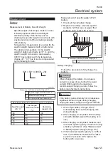
The following describes the state of the
interlock system circuit.
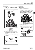
The key switch is in the START position
(starter motor start position).
The brake pedal is pressed (safety switch
ON (pushed)).
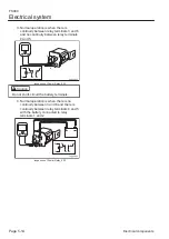
The operator is seated on the seat (seat
switch OFF).
The foot is released from the traveling
pedal (traveling pedal proximity switch OFF
(traveling pump is in neutral)).
The starter motor of the engine in the above
state is running, and the engine can be
started and continually operated.
When the foot is released from the brake
pedal, the safety switch turns OFF, and the
start motor no longer runs.
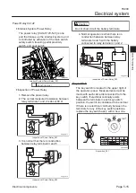
When the traveling pedal is pressed
(forward/reverse), the traveling pedal
proximity switch operates.
Current flows to relay number 5 (CA1aF),
and relay number 6 (602) is activated, and
the starter motor circuit is shut off, and the
start motor does not run.
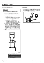
When the operator is not sitting in the seat,
the seat switch signal activates relay
number 8 (602), the starter motor circuit is
shut off, and the start motor does not run.
When the operator gets off the machine
without applying the parking brake while the
engine is running, the signal activates relay
number 8 (602) and the engine is stopped.
When the operator gets off the machine
after applying the parking brake while the
engine is running, the safety switch signal
activates relay number 7 (CA1aF) and the
engine does not stop.
・
・
・
・
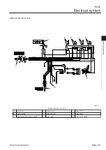
1.
2.
3.
4.
5.
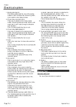
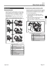
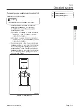
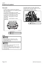
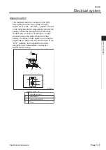
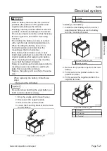
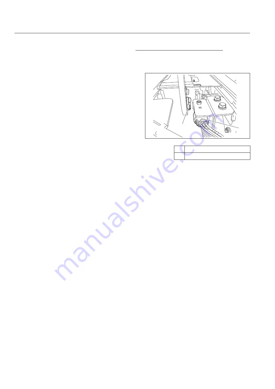
Traveling Pedal Proximity Switch
The traveling pedal proximity switch is an NC
switch that detects that the distance away from
a detected object is increasing.
2
1
lo2wbc-003
Traveling Pedal Proximity Switch_001
1
Traveling pedal proximity switch
2
Plastic magnet
FS900
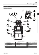
Electrical system
Page 5-10
Electrical components
Summary of Contents for FS900
Page 1: ...Riding Sweeper Service Manual Serial No FS900 10001 Ver 1 0...
Page 4: ...FS900 Contents...
Page 10: ...FS900 Safety Page 1 6 Safety Signs and Instruction Signs...
Page 11: ...Waste Disposal Page 2 2 About the Waste disposal Page 2 2 Disposal FS900 Disposal Page 2 1...
Page 28: ...FS900 Maintenance standards and maintenance Page 3 16 Greasing...
Page 74: ...FS900 Hydraulic system Page 4 46 Inspection and repair of each section...
Page 98: ...FS900 Electrical system Page 5 24 General inspection and repair...
Page 118: ...FS900 Main body Page 6 20 Inspection and repair of each section...