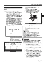
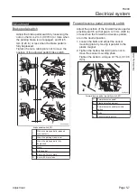
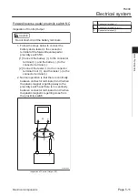
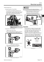
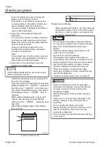
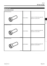
Buzzer Switch
The buzzer switch is located on the operation
panel.
Disconnect the bullet connectors.
2
BUCKET
BUZZER
ON
OFF
1
17kq1q-001
Buzzer Switch_001
1
Toggle switch
2
Bullet connectors
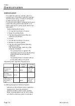
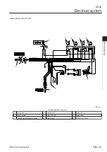
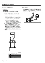
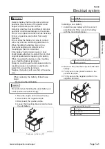
Normally there is conduction between the
connector terminals when the buzzer switch
is set to ON.
Normally there is no conduction between the
connector terminals when the buzzer switch
is set to OFF.
A
B
1
2
A
B
1
2
ON
OFF
17kq1q-002
Buzzer Switch_002
1.
2.
3.
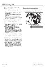
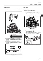
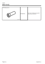
Power Relay
Power Relay 602
Interlock System Power Relay
The power relay [MR5A602A1K] (gray) is
one part that makes up the interlock system,
and is controlled by activation of the main
switch, safety switch, traveling pedal
proximity switch, and seat switch.
1
lqdz5j-001
Interlock System Power Relay_001
1
[MR5A602A1K]
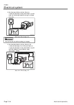
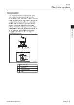
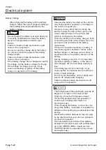
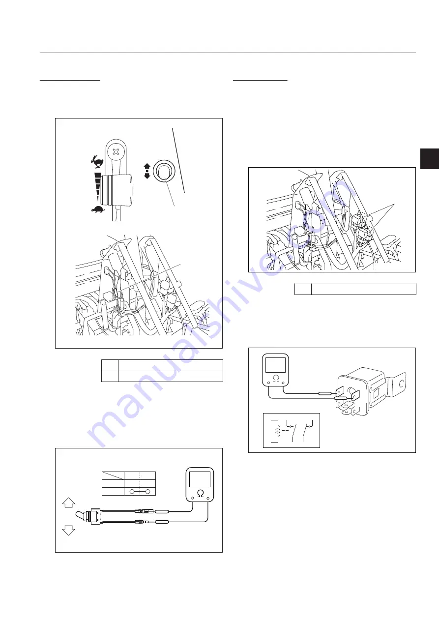
Inspection of Power Relay
Remove the power relay.
The normal measured resistance between
relay terminals 1 and 2 is about 75 Ω.
2
1
4
3
6
5
2
5
6
1
4
3
38jyg3-004
Inspection of Power Relay_001
■
■
1.
2.
Electrical system
FS900
Electrical system
Page 5-13
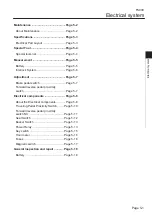
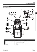
Electrical components
Summary of Contents for FS900
Page 1: ...Riding Sweeper Service Manual Serial No FS900 10001 Ver 1 0...
Page 4: ...FS900 Contents...
Page 10: ...FS900 Safety Page 1 6 Safety Signs and Instruction Signs...
Page 11: ...Waste Disposal Page 2 2 About the Waste disposal Page 2 2 Disposal FS900 Disposal Page 2 1...
Page 28: ...FS900 Maintenance standards and maintenance Page 3 16 Greasing...
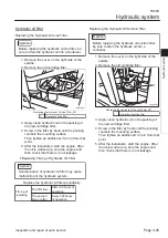
Page 74: ...FS900 Hydraulic system Page 4 46 Inspection and repair of each section...
Page 98: ...FS900 Electrical system Page 5 24 General inspection and repair...
Page 118: ...FS900 Main body Page 6 20 Inspection and repair of each section...


