background image

Rear Cover

Warning

Stop the engine when performing
recommended maintenance operations that
do not require the engine to start when the
rear cover is opened.
When performing maintenance with the
engine started, stay away from moving parts.

Caution

Do not open the cover in strong winds.

Caution

When closing the cover, be careful not to
pinch your hands.

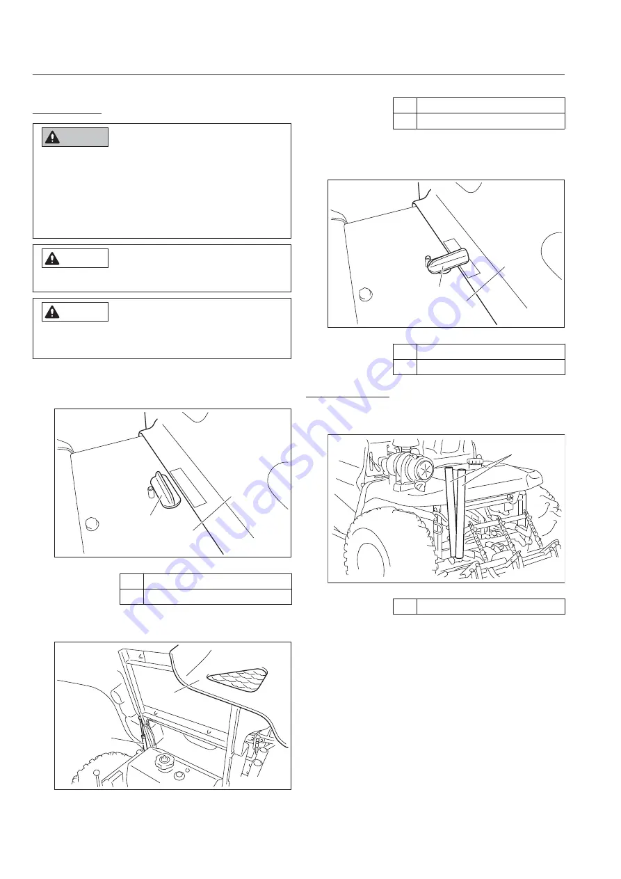
The rear cover is under the seat and is opened
in order to perform maintenance.

Release the cover fastener.

2

1

uemj7o-001

Rear Cover_001

1

Cover fastener (released)

2

Rear cover

Open the rear cover, and then lift it until the
gas spring is fully extended.

1

2

uemj7o-002

Rear Cover_002

1.

2.

1

Rear cover

2

Gas spring

When closing the rear cover, slowly lower it
while firmly supporting it, and then engage
the cover fastener.

1

2

uemj7o-003

Rear Cover_003

1

Cover fastener (engaged)

2

Rear cover

Broom Holder

Broom and rake can be stored in these holders
for transport.

1

mdr5p1-003

Broom Holder_001

1

Broom Holder

3.

SP05A

Handling Instructions

Page 4-24

Operation Method

Summary of Contents for SP05A

Page 1: ...Bunker Rake Owner s Operating Manual Serial No SP05A 20991 Required reading Read this manual before using the machine Original Instructions Ver 1 6...

Page 2: ...nd inspection of your product We hope you will use the product safely and take advantage of its best performance Keeping The Owner s Operating Manual Keep this Owner s Operating Manual in the box on t...

Page 3: ...Co Ltd Warning Symbols This manual uses the following warning symbols for handling precautions that are important for your safety 696cq5 001 Warning symbol This symbol indicates the articles regarding...

Page 4: ...s to thoroughly understand the contents for safe and correct operation Baroness Owner s Operating Manual The Engine s Owner s Manual The Battery s Owner s Manual Purpose This product is intended for l...

Page 5: ...ions Page 4 1 Inspections Page 4 2 Tightening Torques Page 4 11 Adjustment before Work Page 4 14 Procedure to Start Stop Engine Page 4 17 Operation Method Page 4 18 Instruments Page 4 25 Travel of Mac...

Page 6: ...SP05A Contents...

Page 7: ...Safe Operating Practices Page 1 2 Training Page 1 2 Preparation Page 1 2 Operation Page 1 3 Maintenance and Storage Page 1 4 Safety SP05A Safety Page 1 1...

Page 8: ...distribution 1 2 3 1 2 Never allow children or people unfamiliar with these instructions to use or service the machine Local regulations may restrict the age of the operator The owner user can preven...

Page 9: ...e slipping 4 5 6 7 8 1 2 3 4 1 2 3 4 5 6 Use extra care while operating machine with a grass catcher or other attachments They can affect the stability of the machine Never operate the machine with da...

Page 10: ...tely manage and correctly use the tools necessary for servicing or adjusting the machine 16 17 18 19 20 1 2 3 4 5 6 7 8 9 10 Use jack stands to support components when required Carefully release press...

Page 11: ...Recycle and Waste Disposal Page 2 2 About Recycle Page 2 2 About Waste Disposal Page 2 2 Disposal SP05A Disposal Page 2 1...

Page 12: ...economical use of resources It may be required by local laws About Waste Disposal Make sure that waste generated when servicing or repairing the machine is disposed of in accordance with local regula...

Page 13: ...ch Section Page 3 4 Regulation Decals Page 3 4 Positions of Regulation Decals Page 3 4 Description of Regulation Decals Page 3 5 Safety Signs and Instruction Signs Page 3 6 About Safety Signs and Inst...

Page 14: ...asoline 15 0 dm3 15 0 L Fuel consumption 228 g PS h rated output 310 g kW h rated output Engine oil capacity 0 42 U S gal 1 6 dm3 1 6 L Coolant volume Hydraulic tank capacity 3 96 U S gal 15 0 dm3 15...

Page 15: ...procedure specified in ISO5395 1 2013 Vibration Level Hand Arm Vibration This machine was confirmed not to exceed a vibration level of 2 5 m s2 to hands and arms by measuring identical machines in ac...

Page 16: ...selector lever 3WD specifications 11 Brake pedal 12 Tilt lever 13 Throttle lever 14 Up down lever 15 Fuel filler 16 Broom holder 17 Rear cover 18 Fuel cock 19 Finishing brush option Regulation Decals...

Page 17: ...year of manufacture decal indicates the year when this machine was manufactured YEAR OF MANUFACTURE wvzv36 001 Year of Manufacture Decal_001 Battery Capacity Decal For Europe The battery capacity deca...

Page 18: ...tion to getting pinched decal 3 Caution exhaust gas decal 4 Lead free gasoline decal 5 Fire prohibited decal 6 Caution to getting entangled decal 7 Caution for high temperatures decal 8 Caution to noi...

Page 19: ...aution exhaust gas Warning Caution for exhaust gas kvwx52 001 Caution Exhaust Gas Decal_001 Lead Free Gasoline Decal K4209001310 Decal lead free gasoline Use lead free gasoline xmitt2 002 Lead Free Ga...

Page 20: ...to Getting Entangled Decal_001 Caution for High Temperatures Decal K4205001920 Decal caution for high temperatures Caution High temperature Do not touch Otherwise you will get burned xekv4l 001 Cauti...

Page 21: ...t Stop Engine Page 4 17 Start Stop of Engine Page 4 17 Safety Mechanisms Page 4 18 Warning Mechanisms Page 4 18 Operation Method Page 4 18 Cautions for when You Leave The Machine Page 4 18 Positions o...

Page 22: ...e fulcrum fitting Make sure that the rake mounting bracket is not bent Make sure that the smoother plate is not bent cracked or unevenly worn Make sure that the warp board is not bent cracked or worn...

Page 23: ...ks Inspect and if necessary repair or replace Make sure that the brush mounting frame is not bent Make sure that the brush is not bent or excessively worn 1 2 3 4 1 2 Oil Cooler Inspection of Oil Cool...

Page 24: ...dmhzyz 004 Hydraulic Oil Supply_001 1 Dimple knobs 2 Front cover 1 2 3 1 Remove the bolts and then remove the cover 2 1 dmhzyz 002 Hydraulic Oil Supply_002 1 Bolt 2 Cover If the oil level is low open...

Page 25: ...ed nor dirty Make sure that the inner element is neither damaged nor dirty 2 1 5 4 3 pd9d4r 003 Inspection of Air Cleaner_001 1 2 1 Outer element 2 Inner element 3 Clip 4 Cover 5 Air cleaner body Clea...

Page 26: ...m fluid level line U P P E R L E V E L L O W E R L E V E L 1 2 48yhlu 006 Inspection of Battery_001 1 UPPER LEVEL 2 LOWER LEVEL 1 2 Supply of Battery Fluid Danger Danger Be careful not to let your ski...

Page 27: ...muffler is near the belt Inspect the belt after the muffler has sufficiently cooled Press the middle of the belt with your finger to check the belt tension Make sure that there are no cracks damage o...

Page 28: ...of engine oil Important Be sure to use engine oil that is classified as API Service Grade SF or higher with an SAE Viscosity that is appropriate for the operating environment ambient temperature Impo...

Page 29: ...fuel gauge If you supply too much fuel it might overflow from the fuel cap when you travel or work on a slope Warning Keep fire away while refueling Do not smoke while refueling 4 Warning Supply fuel...

Page 30: ...e fuel valve and then clean the fuel strainer in a clean location free of dust and dirt Remove the filter pot wash the filter and inside of the filter pot using a solvent such as a hardly flammable ke...

Page 31: ...table below is for the galvanized or parkerized bolts In case that the strength of internal thread is weak it is not applied Do not use rusty or sand attached screw Otherwise it may cause insufficien...

Page 32: ...99 71 38 44 26 61 96 7 10 71 38 101 97 61 96 88 51 M6 8 11 81 58 112 17 70 81 97 36 14 18 142 76 183 55 123 91 159 32 M8 23 29 234 53 295 71 203 57 256 68 28 38 285 52 387 49 247 83 336 34 M10 45 57...

Page 33: ...M10 20 29 38 295 71 387 49 256 68 336 34 Motor mounting base K0160000492 24 special nut P1 5 180 200 1835 46 2039 40 1593 18 1770 20 Wheel K0014120602 Bolt heat treated M12 60P1 5 67 85 683 20 866 75...

Page 34: ...e steering wheel to the position that suits your work requirements and then shift the tilt lever to the LOCK position to secure the steering wheel in place The tilt lever is located at the center of t...

Page 35: ...mately 200 mm 7 87 in Place a wooden board with a thickness of about 15 mm 0 59 in under the warp board 1 2 1 1 2 Adjust the fork prong bar to a position where the rake load is applied to the wooden b...

Page 36: ...function may not be available The height of the finishing brush can be adjusted by moving the right and left movable arms while griping the right and left clutch levers Return the clutch levers after...

Page 37: ...re that the traveling pedal is in neutral position Move the throttle lever to the middle position between High and Low Pull the choke knob Pull the choke knob half way for restarting as necessary Swit...

Page 38: ...t applying the parking brake The traveling pedal is operated after the parking brake is applied and the operator leaves the seat Warning Mechanisms This machine features a warning mechanism to prevent...

Page 39: ...1 1 OFF 2 ON 3 START Engine Rotation Decal Engine rotation decal This indicates high low speed of the engine rotation 1 2 kp2t9l 002 Engine Rotation Decal_001 1 High speed 2 Low speed Rake Up Down Mar...

Page 40: ...WITCH This indicates the light switch positions 2 1 mzmbmi 006 Light Switch Mark_001 1 ON 2 OFF BRAKE Decal K4203001450 Decal BRAKE This indicates brake BRAKE 7elqr2 001 BRAKE Decal_001 FORWARD Decal...

Page 41: ...lled when starting the engine Pull the knob half way for restarting as necessary 1 2ucrrs 001 Choke Lever_001 1 Choke lever Up Down Switch Lever Important If the engine rpm is low the rake will not be...

Page 42: ...3WD when working on steeply sloped or soft bunkers or bunkers with a small diameter Light Switch Note Depending on the specifications this function may not be available Caution The lights provide aux...

Page 43: ...elease the lock fitting 1 2 iemzu4 002 Brake Pedal_001 1 Brake pedal 2 Lock fitting Front Cover Caution Do not open the cover in strong winds Caution When closing the cover be careful not to pinch you...

Page 44: ...to perform maintenance Release the cover fastener 2 1 uemj7o 001 Rear Cover_001 1 Cover fastener released 2 Rear cover Open the rear cover and then lift it until the gas spring is fully extended 1 2 u...

Page 45: ...truments Instruments on The Operation Panel 1 kz7ka6 004 Instruments on The Operation Panel_001 1 Hour meter Hour Meter 21008 The hour meter is located in the operation panel and indicates the accumul...

Page 46: ...the traveling pedal The machine starts traveling Towing The Machine If the machine does not travel due to engine trouble etc you can move it by towing it Important Do not touch the unload valve excep...

Page 47: ...Rake Warning Do NOT start to move or stop the machine abruptly Caution Perform operations at an appropriate speed for the site and location Caution Before starting operations check that the area where...

Page 48: ...fe Caution Before raising or lowering the rake make sure that there are no people around the rake 6 7 8 9 10 11 Caution If the blade is raised do not touch the lifting lever Caution When getting on an...

Page 49: ...ing operations check that the area where the operations are to be performed is safe Start the engine Procedure to Start Engine Page 4 17 Important If the engine rpm is low the rake will not be raised...

Page 50: ...ormed is safe Start the engine Procedure to Start Engine Page 4 17 Important If the engine rpm is low the rake will not be raised and lowered due to insufficient hydraulic oil Move the throttle lever...

Page 51: ...ransporting Transporting Procedure When loading the machine into a trailer or a truck to transport it drive the machine in reverse When unloading drive the machine forward Storage Before Long Term Sto...

Page 52: ...SP05A Handling Instructions Page 4 32 Storage...

Page 53: ...Change of Small Blade Page 5 9 Change of The Cultivator Fitting Page 5 9 Change of Finishing Brush Page 5 10 Removing Installing Tires Page 5 10 Adjustment of Belt Tension Page 5 12 Adjustment of Ste...

Page 54: ...the maintenance schedule below Inspect adjust supply clean Replace first time Replace Maintenance Item Before work After work Every 8 hrs Every 10 hrs Every 50 hrs Every 100 hrs Every 200 hrs Every 25...

Page 55: ...Fuel strainer Fuel pipe Cleaning the exterior For engine maintenance refer to the Engine s Owner s Manual The values for consumables are not guaranteed Replace the steering cylinder hoses every 2 yea...

Page 56: ...the machine securely with jack stands or appropriate blocks Failure to do so may cause the machine to move or fall resulting in injury or death Use the jack up points identified in this manual when ja...

Page 57: ...left frame rwyt62 005 Jack Up Points_005 2 3 4 Greasing About Greasing Since there may be adhesion or damage due to lack of grease on moving parts they must be greased Add urea based No 2 grease in ac...

Page 58: ...ulcrum 1 1 3 Belt tension lever 1 1 4 Pump neutral lever fulcrum 1 1 5 Front wheel shaft rhombic flange unit 2 1 6 Rear wheel brake lever fulcrum 2 2 7 Blade lever fulcrum 1 1 8 Blade arm fulcrum 2 2...

Page 59: ...bic flange unit 8bq62b 006 Greasing Points_006 Rear wheel brake lever fulcrum 8bq62b 007 Greasing Points_007 4 5 6 8bq62b 008 Greasing Points_008 Blade lever fulcrum 8bq62b 009 Greasing Points_009 Bla...

Page 60: ...0 Location No of lubrica ting points 1 Rake up down cylinder spherical bearing 1 Rake up down cylinder spherical bearing There is one point 8bq62b 462 Lubricating Points_002 Maintenance Work Change of...

Page 61: ...ultivator be careful not to pinch your hands When wear of the trapezoidal cultivator fitting disables unhardening the sand replace the trapezoidal cultivator fitting Remove the bolts at the bottom of...

Page 62: ...e 002 Change of Finishing Brush_002 1 Bolt 2 Finishing brush Tighten the bolts Removing Installing Tires Front Tire Follow the steps below to remove the front tire Securely place the jack beneath the...

Page 63: ...mounting bolt 13 Spring washer C 14 Washer C 15 Front wheel Important Tighten the bolts in the tightening order crosswise For installing the front tires reverse the removing procedure Rear Tires Follo...

Page 64: ...high nut until there is no clearance between the spring cover and the tension fulcrum fitting and then lock it in place with the nut 9 8 7 3 5 4 2 1 6 vottpg 001 Adjustment of Pump Drive Belt_001 3 4...

Page 65: ...the brake pedal will be hard 6 3 1 2 4 5 7 yv5cjg 001 Adjustment of Adjustment Bolt_001 1 Brake pedal 2 Spring rod 3 Adjustment bolt 4 Nut 5 Brake wire 6 Brake lever 7 Rear wheel Adjustment of Spring...

Page 66: ...Start the engine and rev it up to the maximum rpm Set the 2WD 3WD selector lever to the 2WD position Warning When adjusting the neutral position exercise care so that the hand does not get entangled...

Page 67: ...ower the rake and then stop the engine 9 1 1 2 Remove the drain plug of the hydraulic tank and then drain the old oil into a container Wind new sealing tape on the drain plug and then attach it to the...

Page 68: ...that point Supply hydraulic oil until it reaches the specified level Hydraulic Oil Supply Page 4 4 Start the engine and then stop it after 10 to 20 minutes 1 2 3 4 5 Make sure that there is no oil le...

Page 69: ...le the engine oil is warm and then drain the oil into a bowl Wind new sealing tape around the drain plug and then replace it in the engine 1 gui678 007 Change of Engine Oil_001 1 Drain plug 1 2 3 Remo...

Page 70: ...and then hand tighten additional 1 2 to 3 4 turn from that point without using a filter wrench 1 2 3 Supply engine oil until it reaches the specified level Supply of Engine Oil Page 4 8 Start the engi...

Page 71: ...y terminal connections damaged wiring or terminals or incorrect wiring The fuses are located at the lower right inside the front cover and consist of the light harness fuse and the main harness fuse f...

Page 72: ...SP05A Maintenance Page 5 20 Maintenance Work...

Page 73: ......

Page 74: ......

Page 75: ......

Page 76: ...Head Office Tel 81 533 84 1390 Fax 81 533 84 1220 1 26 Miyuki cho Toyokawa city Aichi pref 442 8530 JAPAN SP05A UM GBZ 21A 00 S K E01a SP05A_EU01a...

Reviews: