background image

#0-313A-SBA  (6/01) 
Page 14 of 14 pages 
BARRETT CENTRIFUGALS INC. 
1-800-228-6442 

  The sensor must be secured to the motor housing by the jam nut. 

  The green LED on the sensor should be lit, indicating that it is receiving power. 

  To adjust the sensitivity turn the sensitivity adjustment potentiometer, with a screwdriver, 

all the way in the clockwise direction.  

  With the machine’s lid open, manually spin the machine’s carrier. The yellow LED on the 

sensor should blink, the more speed the more rapid the blinking. 

  When the yellow LED stops flashing the machine is ready to run a cycle. 

 
A flashing output signal from the sensor is interpreted by the PLC as spindle rotation.  If 
the drive motor coil (1M) is energized and the PLC does not receive or loses the rotation 
signal the machine will immediately brake to a stop.  The red light on the machine’s push 
button station will illuminate to indicate a system fault.  The fault signal will only reset when 
the machine’s disconnect is turned off. 


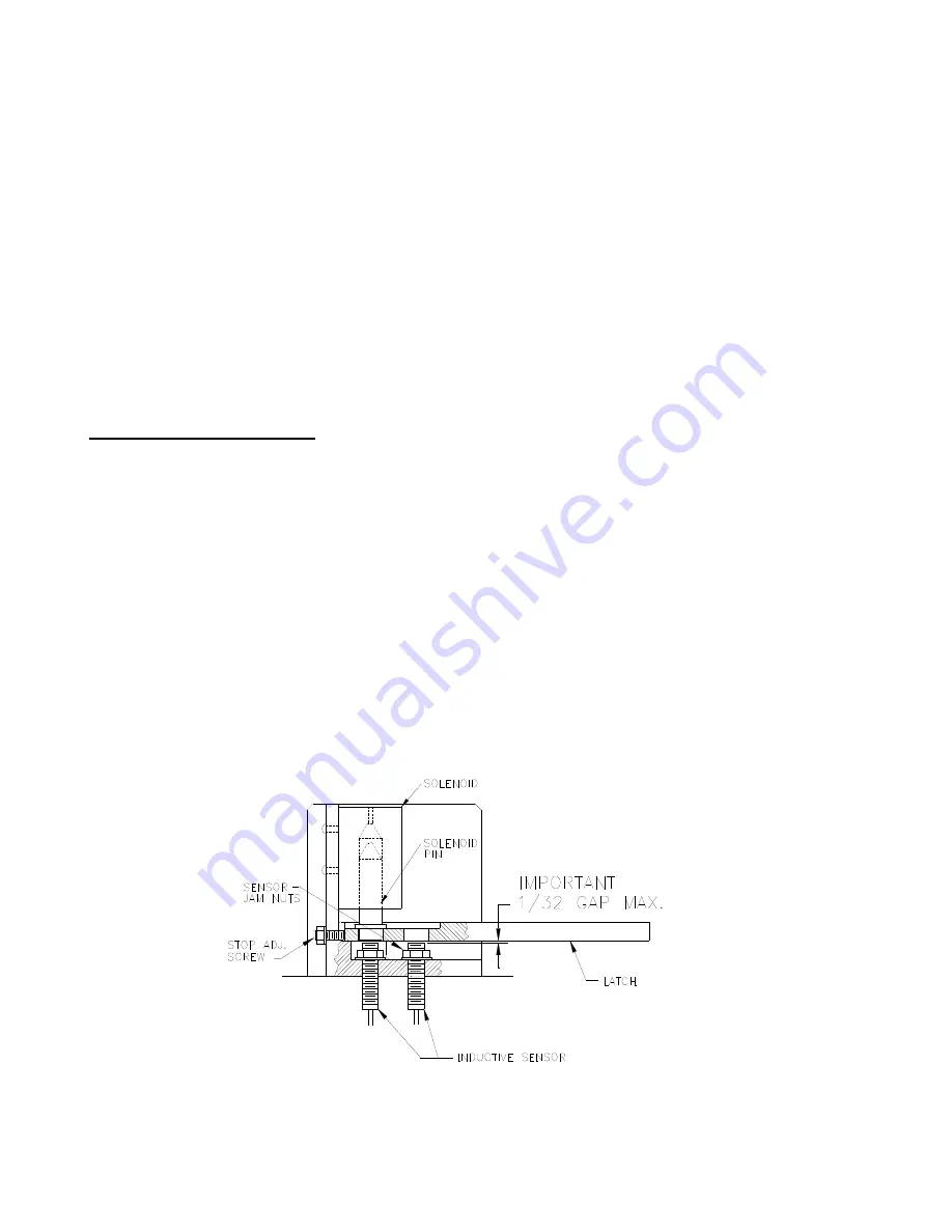
LID LATCH ADJUSTMENT (Ref. to Fig. 4)


Before any maintenance is performed on the lid latch be sure power is off and locked out. To 
remove the sheet metal guard protecting the latch assembly, first remove the front cover of 
the push button station enclosure.  Remove the screws holding the guard in place and slide it 
off of the assembly.  Clean any contamination or build-up from all assembly components (use 
compressed air if available).  If necessary remove the solenoid pin and clean thoroughly.  Be 
sure the pin slides freely in the solenoid cylinder.  

It is very important that the pin is 

aligned properly when the solenoid is fastened to the bracket

 
While manually holding the pin 

up

, slide the lever into its closed position and visually inspect 

the gap between the sensor tips and the bottom surface of the latch. The gap should be 
approximately 0.03 in.  If not, loosen the sensor jam nuts and adjust the height by carefully 
turning the sensor barrel.  Be careful not to over extend the sensor tip as it could be damaged 
if struck by the latch.  If the sensor does not turn freely apply some WD-40 or similar lubricant 
to the threads.  When the sensors are adjusted properly, tighten the jam nuts to 
approximately 48 inch pounds of torque. 

Fig. 4.  

Lid latch components 


Summary of Contents for 1101

Page 1: ...sludge Prior to using it on any other application you should contact Barrett Centrifugals Inc to determine if the machine can be used successfully and safely THIS EQUIPMENT MUST BE INSTALLED WIRED OPERATED AND SERVICED BY QUALIFIED PERSONS ONLY READ UNDERSTAND AND COMPLY WITH THESE INSTALLATION OPERATING AND SAFETY INSTRUCTIONS BEFORE INSTALLING OPERATING OR SERVICING THIS EQUIPMENT SAFETY IS ESSE...

Page 2: ...C and possibly a variable speed drive VFD Altering or tampering with the settings that are programmed into these devices could cause the machine to malfunction It could also lead to failure of the safety controls and devices meant to protect personnel and change the motor speed that could severely damage the machine Only qualified personnel should attempt to change the settings Before attempting a...

Page 3: ...through bolts On concrete floors Barrett recommends the use of epoxy set type anchors to secure the machine to the floor The machine must be absolutely solid with the floor Do not set in wet cement Do not run machine without anchoring or vibration may allow it to move about and damage the electrical connections WIRING The wiring of this equipment should be performed by a qualified electrician and ...

Page 4: ...the right hand side of the machine the customer must provide a source of clean dry ambient air piped to enter the blower Failure to comply may allow dry chips being dumped to be sucked into the blower and result in an accumulation of foreign material within the motor ultimately causing premature motor burnout THE ROTATION DETECTOR DC BRAKE The Rotation Detector and DC Brake circuit designed for th...

Page 5: ...t to the PLC If the sequence is verified and completed in the given amount of time a flashing green light indicates that the machine is properly latched and ready to start If the green light does not flash simply retract the lever all the way to the right and start the process over 4 When the START push button is pressed the solenoid pin drops and the green light goes out The pin prevents the latc...

Page 6: ... the weight of a load Do not be tempted to exceed the load sizes noted above They will accommodate most sludge types Remember a pound of sludge will effectively weigh hundreds of pounds under centrifugal force Overloading may cause machine failure and damage to the machine or injury to personnel Do not overload THE 1101 E AND 1101 SES PANS AND COVERS ARE MATCHED SETS AND ARE NOT INTERCHANGEABLE DO...

Page 7: ...anel 10 When the green OPEN signal lights the cycle is complete USE AND CARE OF FILTER ELEMENTS AND SPOKED PAN SES MODEL MACHINE Barrett SES type machines are equipped with special pans and filter elements that maximize the efficiency of the liquid extraction The spokes on the pan create a path for liquid to escape The polypropylene or cotton filter elements retain the sludge in the pan 1 Placemen...

Page 8: ...operating this machine use care to load the pan evenly to insure a good running balance Make sure that all guards and covers are in place 1 Before operating the machine be sure that provisions have been made to capture the extracted liquid from the outlet at the rear of the machine 2 Adjust the cycle timer s 1TRE located within the control panel Barrett recommends an initial setting of 30 minutes ...

Page 9: ...hat it is securely attached Fold the upper half of the side filter which has been draped outside of the pan for sludge loading up and over the load resting it on top of the wet sludge The side filter must be completely within the pan and positioned so it will not be pinched between the pan s top edge and the cover 8 Loading a pan whether empty or full of sludge into the machine will require a hois...

Page 10: ... pan guide tool and spindle of the machine until it comes to rest on the pan support Release the hoist and remove the pan guide tool 13 Attach the spindle nut onto the spindle s threaded top LOCK THE PAN COVER ONTO THE MACHINE S SPINDLE This is extremely important If not done correctly the pan or cover or both may be damaged Other machine components could be damaged or injury to the centrifuge ope...

Page 11: ...r is disconnected the machine will coast to a stop which could take up to 15 minutes OUT OF BALANCE SWITCH OPTIONAL ON SOME MODELS All model 1100 and some 400 machines are equipped with an out of balance switch These switches are located on the underside of the drum s floor In the event of any severe vibration the switch is activated Immediately the cycle in progress is terminated and the machine ...

Page 12: ...ould be replaced as a complete set 4 in the event of any spring failure 2 On machines equipped with a motor cooling blower the blower inlet screen must be inspected weekly If the screen is plugged with dirt remove it and simply clean it with compressed air DO NOT ATTEMPT TO CLEAN THE SCREEN WHILE THE BLOWER IS RUNNING AS DIRT WILL BE BLOWN INTO THE MOTOR Be sure to reinstall the screen after clean...

Page 13: ...E IS RUNNING To plumb the spindle remove tension from the four balancing springs by backing off the jam nuts Plumb the rotating element using a level on top of the flat machined surface of the carrier or pan support Screw the bottom four nuts down until they bear lightly and evenly on all four springs and the carrier registers plumb Tension at this point should be such that the springs can be turn...

Page 14: ...fore any maintenance is performed on the lid latch be sure power is off and locked out To remove the sheet metal guard protecting the latch assembly first remove the front cover of the push button station enclosure Remove the screws holding the guard in place and slide it off of the assembly Clean any contamination or build up from all assembly components use compressed air if available If necessa...

Page 15: ...nd enclosure cover when complete BEARINGS The bearings in this machine are for centrifugal application having special internal fits and should be purchased from Barrett REPAIR PARTS Repair parts are available from Barrett Centrifugals Inc 156 Goddard Memorial Drive Worcester MA 01603 Telephone 800 228 6442 or 508 754 6891 Fax 508 756 5342 E mail sales Barrettinc com Web Site Barrettinc com Be sure...

Reviews: