#0-313A-SBA (6/01)
Page 4 of 14 pages
BARRETT CENTRIFUGALS INC.
1-800-228-6442
voltage wiring and control wiring should be fed through separate conduit lines to avoid faulty
signals generated by electrical noise.
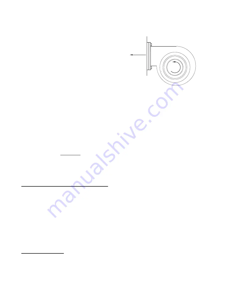
Fig. 1.
Motor cooling blower
Machines supplied with a motor driven cooling
blower are factory wired so that the blower must
be on for the machine to operate. The motor
cooling blower is set at the Barrett factory to
remain on for 10 minutes after a cycle ends.
Rotation of the blower (if provided) and main drive
motor will have to be checked after power to the
control panel has been obtained. To check the
rotation, push the
START
push button and
immediately cut power to the machine by turning the main disconnect on the control panel to
Off.
Observe the direction of the blower motor as the blower fan coasts to a stop. It should be
rotating counterclockwise when viewing from the front of the machine (blowing cool air into
the machine). To change blower rotation, disconnect the power supply and switch two of the
power leads supplying the main disconnect. This insures that when the blower is rotating
properly all other components are rotating properly as wired at the factory.
Ground all equipment according to OSHA Electrical Standards, the National Electrical Code
and local codes.
NOTE: For all machines with a motor cooling blower, and trunnion dump arms
mounted on the right-hand side of the machine the customer must provide a source of
clean, dry, ambient air piped to enter the blower. Failure to comply may allow dry
chips being dumped to be sucked into the blower and result in an accumulation of
foreign material within the motor, ultimately causing premature motor burnout.
THE ROTATION DETECTOR / DC BRAKE
The Rotation Detector and DC Brake circuit designed for this machine are intended for the
operator's safety. The machine cannot be started unless the lid is closed and the lid latch is
locked. Once the machine has been started the lid cannot be opened until the rotating
assembly has come to a complete stop. A green signal light located on the push button
station will light up, indicating that the machine has stopped spinning. When the green light is
illuminated the lid latch can be disengaged and the lid opened. The rotating assembly is
brought to a stop with a D.C. braking circuit that works in conjunction with a photoelectric
sensor and the PLC (Programmable Logic Controller) located within the control panel.
In the event of a power failure the lid latch will stay locked to prevent premature opening of
the lid. There is no manual bypass.
SAFETY LID LATCH
(Refer to Fig. 2)
This machine is equipped with a safety lid interlock that works in conjunction with the DC
brake circuit, rotation sensor and PLC to prevent opening of the lid while the machine is
rotating. The solenoid pin in the latch housing provides the necessary mechanical lockout.
The machine cannot be started with the lid open or the latch unlocked.
If in the locked


