background image


1

2

34

A

B

C

D

4

3

2

1

D

C

B

A

R1

1K

R3

390K

R5

5K

6

R7

10K

VP

SU

VPSU

C1

0U1

R2

1K

R6

24K

R8

39K

VB

a

tt

VB

a

tt

3

12

2

5

4

U1A

L

M

339

-2

1

7

6

U1

B

L

M

339-

2

14

9

8

U1

C

LM

339-

2

13

11

10

U1

D

LM

339-

2

Ba

tter

y

 sw

it

ches 

o

u

t at

 1

1

V

and 

s

tay

s

 l

atc

hed

 unti

l M

ai

n

s

 r

et

ur

n

s

 o

batte

ry

 i

s

 r

e

pl

a

c

ed

P

S

U

 s

w

it

c

h

e

s

 out

 at 

10.

5

v

P

S

U

 s

w

it

c

h

e

s

 in

 a

t 1

1

v

R1

3

15

K

Vi

n

R1

0

15K

R1

1

1K

VP

SU

+1

3

V

8

VB

a

tt

R1

2

1K

VB

att

R14

1K

VB

att

R1

6

100K

R1

7

100K

PSU

+

PSU

-

BA

T

T

-B

BA

T

T

-G

D7

LED

 Gr

een

GR

E

E

N

R

ED

D9

HL

M

P

-0

80

0

D8

BA

V70

Vi

n

U2

LM

4040DI

M

3

-50

U3

LM4

040DIM3

-50

R1

8

3K

9

R1

9

82K

Q1 BSP

1

7

C2

10U

C3

47

U

Q3

2

N

7002

R4

10K

V

PSU

Q2

ND

T45

6

D1

BA

V

7

0

C4

0U

1

1

2

3

4

5

6

P1

CO

N6

R

ear

 Pa

n

e

l

VBatt

V

PSU

+1

3

V

8

S

peak

er

Con

trol

VBat

t

VP

SU

Vi

n

D2

BA

V70

1

2

SPK

1

CO

N

2

1

2

SPK

2

CO

N

2

C5

0U1

R9

1K

Bar

re

tt 2022 Power

 Supply 

Fr

ont Pane

l Schematic

Dr

awing No

: 2022

D02-

A2

    5


Summary of Contents for 2022

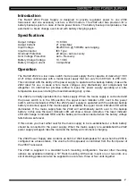
Page 1: ...ommunications Head Office Barrett Communications Pty Ltd 47 Discovery Drive Bibra Lake WA 6163 Australia Tel 61 8 9434 1700 Fax 61 8 9418 6757 Email information barrettcommunications com au www barrettcommunications com au ...

Page 2: ...ated from a mains supply When the mains supply is connected and the power switch is in the ON position the upper Green indicator LED next to the power switch will be illuminated When the 2022 power supply is operated with the optional backup battery connected again if the mains supply is available the upper Green indicator LED will be illuminated If the mains supply fails the 2022 will automatical...

Page 3: ... off battery voltage low and no power being supplied to the load In the first situation with the switch mode ON and the battery being charged U1C has no control over the relay RL1 In this operating state the switch mode module is keeping the output of U1B LOW and the Relay RL1 switched to provide the output voltage from the switch mode module Once the switch mode module fails either due to a fault...

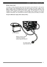
Page 4: ...ry charge current is controlled by R9 and RT1 If the battery charge is low then it will demand a higher charging current from the power supply This will cause RT1 to heat up resulting in an increase in the resistance of the thermistor and a reduction in the current supplied to the battery This circuit limits the maximum charge current to the battery to 3 Amps Using the 2022 power supply with a bac...

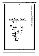
Page 5: ...5v PSU switches in at 11v R13 15K Vin R10 15K R11 1K VPSU 13V8 VBatt R12 1K VBatt R14 1K VBatt R16 100K R17 100K PSU PSU BATT B BATT G D7 LED Green GREEN RED D9 HLMP 0800 D8 BAV70 Vin U2 LM4040DIM3 50 U3 LM4040DIM3 50 R18 3K9 R19 82K Q1 BSP17 C2 10U C3 47U Q3 2N7002 R4 10K VPSU Q2 NDT456 D1 BAV70 C4 0U1 1 2 3 4 5 6 P1 CON6 Rear Panel VBatt VPSU 13V8 Speaker Control VBatt VPSU Vin D2 BAV70 1 2 SPK1...

Page 6: ...6 ...

Page 7: ...Barrett 2022 Power Supply Front Panel PCB Drawing No 2022P02 A2 7 ...

Page 8: ...19 R4 Res 10k 5 0 063W 0603 NB RE 10277 R5 Res 5k6 0 063W 5 0603 NB RE 10328 R6 Res 22k 0 063W 5 0603 NB RE 10311 R7 Res 10k 5 0 063W 0603 NB RE 10277 R8 Res 39k 0 063W 5 0603 NB RE 10322 R9 Res 1k 5 0 063W 0603 NB RE 10287 R10 Res 15k 0 063W 5 0603 NB RE 10307 R11 Res 1k 5 0 063W 0603 NB RE 10287 R12 Res 1k 5 0 063W 0603 NB RE 10287 R13 Res 15k 0 063W 5 0603 NB RE 10307 R14 Res 1k 5 0 063W 0603 N...

Page 9: ...out 13V8 out Fan Fan VBatt VPSU RL1 REL EP1 3L1S SPDT R9 0 1R 5W D3 1N5821 RT1 THERMISTOR 1 2 P5 CON2 Fan D4 1N5404 13V8 VBatt VPSU VPSU VBatt 13V8 VBatt Battery Charging circuit 1 2 3 4 5 6 P4 CON6 Control Board C5 0U1 VBatt VPSU 13V8 Speaker Control D1 1N4148 D2 1N4148 D5 1N4148 Barrett 2022 Power Supply Rear Panel Schematic Drawing No 2022D1 A5 9 ...

Page 10: ...2022 Power Supply Rear Panel PCB Drawing No 2022P01 A5 10 ...

Page 11: ...914 1N4148 DI 03302 D3 Di 1N5821 Power DI 03353 D4 Di 1N5404 Power DI 03313 D5 Di 1N914 1N4148 DI 03302 P1 Conn D 7W2 2P 5D M ST CN 24150 P2 Conn D 7W2 2P 5D F ST CN 24149 P3 Conn D 7W2 2P 5D F ST CN 24149 P4 Plug 6 pin Polarised CN 14106 P5 Plug 2 pin Polarised CN 14101 R9 Res 0R1 5W WW RE 00751 RL1 Relay EP1 3LIS NEC RL 05020 RT1 Fuse Resettable Polyswitch 4A FU 02534 ...

Page 12: ...nty shall not cover any abuse accident improper installation connection adjustment or use other than in accordance with the instructions issued by the company In addition this warranty shall not cover the distance which transceiver products will operate over or quality of transmission or reception as a result of unfavourable environmental conditions Nor shall this warranty cover the quality of tra...

Page 13: ...t Barrett Communications will provide you with direct access to a support telephone contact line manned from 0000hrs GMT to 1600 Hrs GMT 7 days a week The registration forms can be returned by mail no postage stamp required in Australia or by facsimile 08 9418 6757 International 618 9418 6757 If you have access to the Internet you can use the warranty registration page in the support section of ou...

Reviews: