background image

15

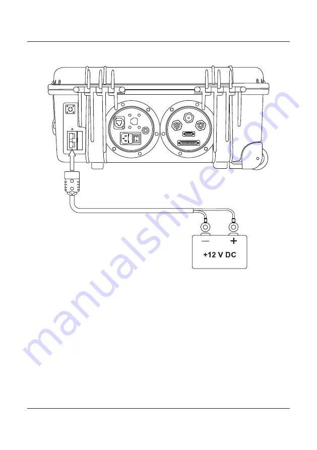
External Battery

To power the 4050 Transporter by external battery follow the below procedure:

1. 

Disengage the circuit breaker

2.  Disconnect the internal battery by reversing step 9 of the previous section.

3.  Connect  the  red  and  black  fittings  to  the  appropriate  terminals  on  the 

external battery.

4. 

Connect the Anderson plug to the connector on the rear of the case as 

indicated above.

5. 

Connect the second Anderson cable on the inside of the case to the Inter-

nal/External connection for internal DC power (DO NOT RECONNECT THE 

INTERNAL BATTERY)

6.  Power on the 4050 transceiver.

Summary of Contents for 4050

Page 1: ...BCM405051 1 Barrett Communications Head Office Barrett Communications Pty Ltd 47 Discovery Drive Bibra Lake WA 6163 Australia Tel 61 8 9434 1700 Fax 61 8 9418 6757 Email information barrettcommunications com au www barrettcommunications com au ...

Page 2: ......

Page 3: ...g the Battery 11 External Battery 15 Mains Power 16 CHARGING 3 17 Solar Panel Charging 18 Setting the Charge Profile 18 Vehicle 12V Accessory Port Charging 20 The ARK Battery Charger 20 DC DC Charging 21 Selecting Battery Profile 22 Charge Screen 23 Further Information 23 Mains Power Charging 25 Warranty Statement 27 Contact Details 28 ...

Page 4: ...4 ...

Page 5: ...anner between the AC and DC sources An internal 7 Amp multi profile AC DC DC DC battery charger keeps the internal and or external battery ready for use whilst AC power is available or connected to vehicle DC outlet This internal charger also displays battery status information Charging is also available via the onboard Victron SmartSolar charge regulator configurable via bluetooth and a convenien...

Page 6: ...d for optimal connec tor protection without compromising quick and easy access To access the connectors turn the lids anti clockwise and remove Reference Description 1 Solar panel input Barrett solar panel only P N BCA209010 2 Anderson connector input for external battery ...

Page 7: ...r Ports Left Reference Description 1 Ethernet connection 2 Mains AC power connection includes AC fuse and on off switch 3 DC In from vehicle DC accessory outlet cig lighter socket 4 Earth ground stud 1 2 3 4 ...

Page 8: ...8 Rear Ports Right Reference Description 1 Antenna In 2 ATU connector 3 GPS Connector 4 Remote Head connector DB 15 5 Accessory connector DB 25 1 2 3 4 5 ...

Page 9: ... and DC DC charging switch 3 Resettable circuit breaker Battery isolator 4 4050 transceiver control head 5 4050 hand microphone and clip 6 DC Battery 7 Internal External connection for DC power 8 4050 transceiver body with fan unit 9 Battery hold down bracket 1 2 3 4 5 6 7 8 9 ...

Page 10: ...10 ...

Page 11: ...TION MAINTENANCE ON THE 4050 TRANSPORTER THE TRANSCEIVER MUST BE REMOVED BEFORE THE BATTERY CAN BE INSTALLED To remove the transceiver disengage the circuit breaker and disconnect all rear cables Hold down the two black tabs on the right hand side of the transceiver mounting plate while slightly lifting the transceiver Pull the transceiver to the right and then up to release it Disconnect the remo...

Page 12: ...racket in place NOTE the battery rod has two available positions on the left of the case by moving the retaining saddle up or down Select the position that allows the battery rod to be angled downwards slightly i e so the lowest point of the rod is on the left 5 Insert the two supplied setscrews into the appropriate holes in the battery hold down bracket so that they pass through the cor respondin...

Page 13: ...ure the set screws into the securing bracket 7 Push the battery hold down bracket and battery tight against the left hand side of the case Hold in position and tighten the set screws the rest of the way CAUTION Do not over tighten 8 Fit the supplied washers and spacers largest to smallest with the wingnut last Tighten until just secure DO NOT OVERTIGHTEN THE WINGNUT ...

Page 14: ...er and lock transceiver body back into the mounting plate 11 Replace rear cables and engage the circuit breaker Internal DC battery power is now available to the transceiver When circuit breaker is engaged power will automatically be supplied to the transceiver i e the transceiver will be live ...

Page 15: ...he previous section 3 Connect the red and black fittings to the appropriate terminals on the external battery 4 Connect the Anderson plug to the connector on the rear of the case as indicated above 5 Connect the second Anderson cable on the inside of the case to the Inter nal External connection for internal DC power DO NOT RECONNECT THE INTERNAL BATTERY 6 Power on the 4050 transceiver ...

Page 16: ...To power the 4050 Transporter by mains power follow the below procedure 1 Connect the power plug to the socket in the left rear port of the case 2 Flip the switch next to the connection 3 Power on the 4050 transceiver ...

Page 17: ...or DC vehicle power via the vehicle s 12V Accessory port cigarette lighter via AC DC Battery charger AC Mains Power via AC DC Battery charger The external battery can be charged as per the above however it is important to note that the correct profiles and parameters must be set for the specific battery being used ...

Page 18: ... damage to the battery It is recommended to check the set charge profile regardless of whether the 4050 Transporter has been sup plied with or without an internal bat tery 1 Download the Victron Connect app from https www victrone nergy nl support and down loads software the App Store or Google Play 2 Turn on device bluetooth 3 Open App 4 Select the Victron SmartSolar MPPT100 15 charger from the D...

Page 19: ...9 Ensure that the Barrett solar panels are placed in full sun 1 Connect solar panel cable to the solar charger port on the rear of the case as shown above 2 Flip the red internal switch to Solar Charging ...

Page 20: ...20 Vehicle 12V Accessory Port Charging The ARK Battery Charger Reference Description LCD Screen Power and info button OK button Down button Up button ...

Page 21: ...the rear of the 4050 Transporter and the vehicle accessory port cigarette lighter 2 Flip the red internal switch to DC DC Charging 3 Press to power on the charger To turn the charger off press and hold for 4 seconds During charging pressing will display the information screen ...

Page 22: ...ocess 2 The AC DC charger can charge four types of batteries 12V lead acid Cal cium GEL or AGM Use the and keys to select correct battery type Press to confirm Note Refer to the battery label or battery manufacturer if battery type is unclear Setting the wrong profile may result in damage to the battery If Calcium battery is selected additional confirmation is required as Calcium batteries charge ...

Page 23: ...r is faulty If this occurs during charging from AC mains check that the circuit breaker is engaged Low Battery Battery voltage is less than 10 5 the AC DC battery charger will switch off after 5 mins Check Battery Battery won t reach boost cycle within 25hours Battery may have a problem i e may be sulphated or have a faulty cell This alarm may be triggered if the battery is used to power a device ...

Page 24: ...onstant voltage of between 14 1V 14 9V depend ing on battery type for 2 hours Amps will vary during 2 hour period Once the battery reaches the target voltage the charger will begin to reduce the amperage and the bulk cycle commences When the amps drops to 4 5A the Ark Battery Charger will reach boost cycle This takes the battery up to 100 charge at the end of 2 hours If the battery does not reach ...

Page 25: ...sporter as indicated above when connected to mains power the AC DC power supply sends 12V DC power to the AC DC charger 2 Turn on battery charger and follow the steps to set charge profile on page 22 Charging and transceiver use can be simultaneous when using mains power ...

Page 26: ...26 ...

Page 27: ... to Barrett Com munications Pty Ltd head office or to an authorised service centre The repaired or replaced product will remain covered under and throughout the term of the original warranty period up to its expiration No repair or replacement will extend the warranty term past the original thirty six 36 month anniversary of the original date of shipment from the Seller Firmware and software pre i...

Page 28: ...communications com au support Barrett Communications Pty Ltd Head Office PO Box 1214 Bibra Lake WA 6965 AUSTRALIA Toll Free Tel 1800 999 580 Within Australia Tel 618 9434 1700 Fax 618 9418 6757 email support barrettcommunications com au Telephone support from the Australian office is available from 7 30 am to 4 00 pm local time Monday to Friday Barrett Communications Europe Unit 9 Fulcrum 2 Victor...

Page 29: ... www barrettcommunications com au Europe Barrett Communications Europe Unit 9 Fulcrum 2 Solent Way Whiteley Hampshire PO15 7FN United Kingdom Tel 44 0 1489 880 332 Fax 44 0 1489 565 422 Email uksales barrettcommunications co uk USA Barrett Communications USA LLC 90 Office Parkway Pittsford NY 14534 United States of America Tel 1 585 582 6134 Email sales barrettusa com ...

Reviews: