background image

4

Installation - Inverted V

1.  Take the antenna in its box to its installation point, below the hoisting halyard. 

2.  Carefully remove antenna from box and - with 

RESISTOR LOADS FACING DOWN -

 lay on ground. Ensure wires do 

not tangle. 

DO NOT REMOVE TAPE OR CABLE TIES.

3.  Remove balun and Inverted V mounting kit from box.
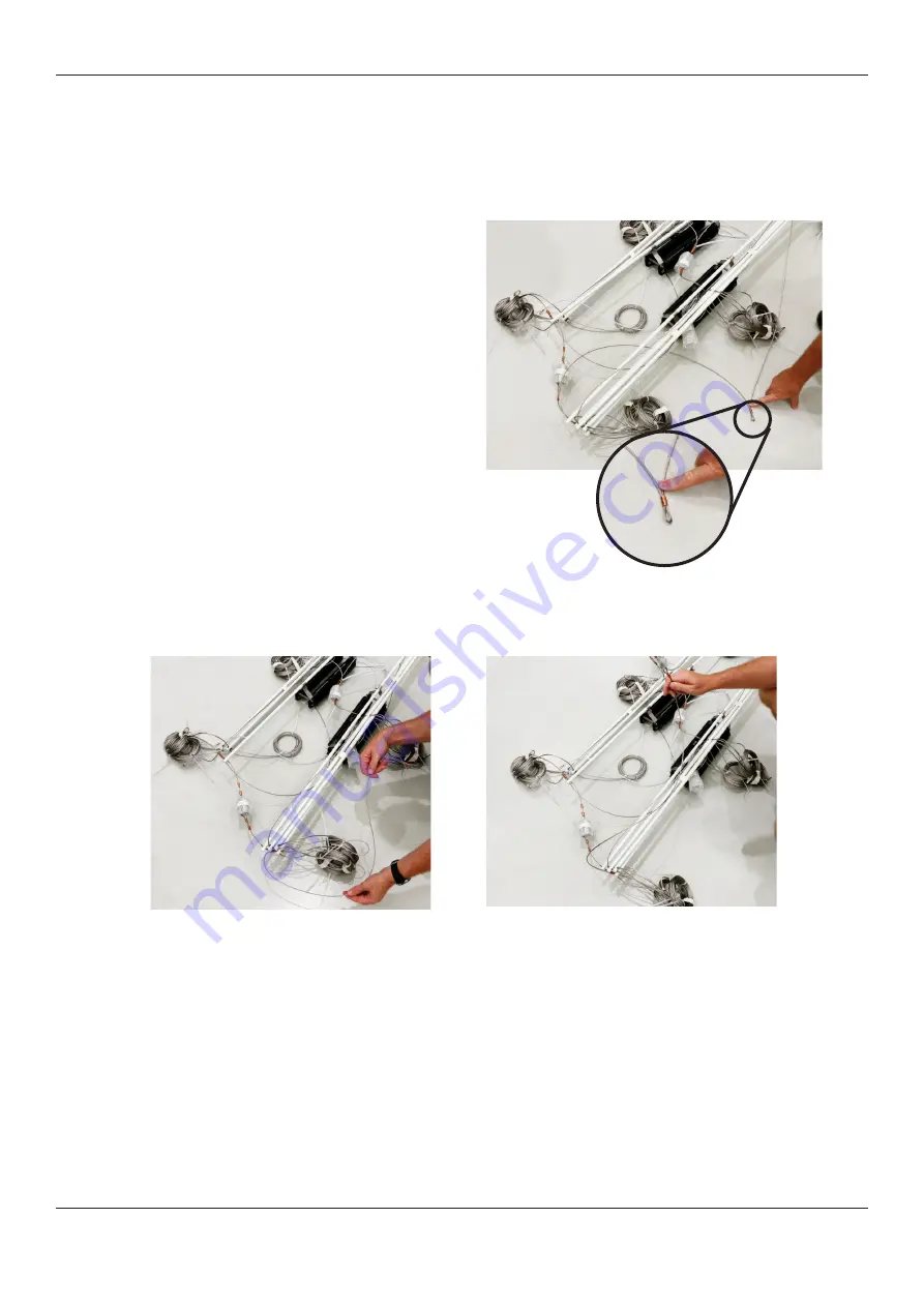
4.  Locate the ‘drop wires’. These will be under the 

antenna. 

5.  Locate the ‘eye loop’ in the centre of the drop wire 

and determine to which half of the antenna it is con-

nected.

6.  Pull the loop along the ground so that it clears the spreader rods and coiled wires and loop the cable over the ends 

of the antenna until it is vertical.

7.  Repeat for the other side.

Eye loop

Summary of Contents for 912

Page 1: ...User Guide 912 Multi wire Broadband Dipole Antenna 500W P N BC91202 27m P N BCM91202 6 Barrett Communications ...

Page 2: ...r to secure the antenna ends In this configuration the mast must also have an offset or out rigger bracket at least 0 8 metres long to hold the antenna away from the mast Barrett can supply a offset bracket and pulley system BCA90200 As with all antenna installations ensure the antenna is as far from sources of electrical interference as possible and in a position that makes it impossible for the ...

Page 3: ...uration the radiation is broadside to the antenna i e if transmissions need to travel in a predomi nantly North South direction the antenna should be set up with the ends pointing East West N N For Inverted V the antenna becomes more suitable for NVIS with radiation being directed at high angles but omnidirec tional around the antenna on a horizontal plane ...

Page 4: ...VE TAPE OR CABLE TIES 3 Remove balun and Inverted V mounting kit from box 4 Locate the drop wires These will be under the antenna 5 Locate the eye loop in the centre of the drop wire and determine to which half of the antenna it is con nected 6 Pull the loop along the ground so that it clears the spreader rods and coiled wires and loop the cable over the ends of the antenna until it is vertical 7 ...

Page 5: ...o the suspension yoke and slowly raise the balun until the connecting wires have taken some weight 10 Further tighten the nuts on the balun 11 Replace the insulated wire connected to one of the load resistor pairs with the longer insulated wire from the Inverted V mounting kit and connect it to the top of the balun ensuring that it passes between the vertical cables see below ...

Page 6: ...gth see below right Ensure that tangles are avoided 3 Carefully hoist antenna to full height 4 Attach appropriate cord to the insulator at each end of the antenna Tie these cords to convenient points to secure the antenna in position These should ideally be tied at a height or in a safe area to avert possible contact and risks of minor shocks or burns 1 2 3 4 5 6 1 Suspension Yoke Eye Loop 2 Suspe...

Page 7: ...e tape and cable ties and extend each section one at a time until extended to full length see below Ensure that tangles are avoided 4 Attach ends of antenna to hoisting halyards and hoist until antenna is at a workable height off the ground Note that the drop wires should be hanging below the hoisted antenna 5 Attach the drop wire loops to the sides of the balun and the insulated wire connected to...

Page 8: ...nd fit with pigtail coax strain relief fitting see right 2 Hoist antenna to full height and secure Note the antenna will curve downward slightly when suspended 1 Insulated Wire 2 Balun 3 Strain Relief Connection Point 4 Coax Cable 5 Pigtail Coax Strain Relief Fitting 1 2 3 4 5 ...

Reviews: