WAM Arm – User’s Manual
support@barrett.com
www.barrett.com
© 2008 Barrett Technology®, Inc.
Document: D1001, Version: AH.00
13 of 80
1.2 System
Options
1.2.1 WAM
Wrist
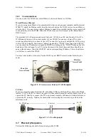
The WAM Wrist module, shown in Figure 11, replaces the outer link of a four-degree-of-freedom
WAM, adding joints 5, 6, and 7, for another three degrees of freedom. Mechanical and electrical
quick-connect features make it easy to swap between the WAM’s outer link and the Wrist module
to convert between 4-DOF and 7-DOF configurations.
In order to minimize the inertial effects of the motors on the host robot arm, the servomotors for
joints 5 & 6 are located at the base of the wrist. The final roll joint in the WAM Wrist, motor joint
7, is the only geared axis. At very small scales, such as at joint 7, gears have slightly better
performance than cables in terms of compactness.
Figure 11 – WAM Wrist
The WAM Wrist comes with its own separate maintenance kit (shown in Figure 12), which
contains:
•
1 Roll 6-mm (¼") wide Masking Tape
•
1 Wrist Tension Tool
•
1 Joint-7 Spanner Tool
•
1 Pull Hook
•
1 Wrist Safety Termination (Packaged separately from the rest of the Maintenance Kit)
Thread for quick-
connect to WAM Arm
Removable transmission cover


