background image

WAM Arm – User’s Manual 

support@barrett.com 

www.barrett.com


© 2008 Barrett Technology®, Inc. 

Document: D1001, Version: AH.00 

16 of 80 


1.2.4 

Control Software/Firmware Upgrades 

Barrett Technology releases software and firmware upgrades periodically (see Section 4.5 for 
details on firmware upgrades). Upgrades are available free of charge for customers of Barrett’s 
support subscription service. Customers with an expired support contracts can choose to renew 
their contract, or purchase the upgrades separately. See the enclosed Support Reference Sheet for 
more information about your support subscription service.  

2  Safety and Cautions 

2.1 Safety 

Instructions 

PLEASE READ THIS SECTION IN ITS ENTIRETY BEFORE USING YOUR WAM. 
 
Following these safety instructions will help prevent user injury and equipment damage. 


Proper precautions should be taken when selecting the location and setup of your WAM 
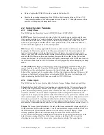
system. DO NOT set up the system such that any part of the robot’s workspace (resembling a 
sphere with an approximately one meter radius, as shown in Figure 16) reaches into a 
pedestrian pathway in the lab space. The WAM is an unusually quiet mechanism – it 
generates little servo or transmission noise – thereby providing very little intrinsic warning of 
its enabled state. 


Figure 16 – WAM Workspace 


In addition, as with any piece of robotic equipment, it is ultimately up to you to be aware of 
your surroundings during robot operation. Although the WAM is intrinsically safer than other 
robotic systems, you may wish to integrate standard safety measures such as mats, gates, light 
curtains, etc. into the lab space surrounding the WAM. 


NEVER connect or disconnect any electrical cables while the Power Supply is turned on. 
Failure to follow this instruction could impart irreparable damage to the onboard electronics 
or put you at risk of electrical shock.  


Always plug the Power Supply into a properly grounded wall source. Failure to do so could 
damage the WAM electronics and put you at risk of electrical shock. 


Do not allow the WAM to be exposed to liquids that may cause electrical short-circuit and put 
you at risk of electrical shock. 


Keep dirt and debris away from the exposed cable drives located at the joints. 


Do not exceed the load limit of the arm: 4 kg for a 4-DOF WAM and 3 kg for a 7-DOF 
WAM. Consider all loading situations including accelerated loads, cantilever loads from long 
objects, robot collisions, active loads, etc. 


Summary of Contents for WAM Arm

Page 1: ...WAMTM Arm User s Manual Document D1001 Version AH 00 ...

Page 2: ...Passive Gimbals 14 1 2 3 External WAM PC 15 1 2 4 Control Software Firmware Upgrades 16 2 SAFETY AND CAUTIONS 16 2 1 SAFETY INSTRUCTIONS 16 2 2 SAFETY SYSTEM PENDANTS 17 2 2 1 Safety States 17 2 2 2 Status Lights 17 2 3 HANDLING SAFETY FAULTS 18 3 SYSTEM SETUP 19 3 1 MOUNTING 19 3 2 GROUNDING 20 3 3 INSTALLING THE EXTERNAL PC OPTIONAL 20 3 3 1 Physical Installation 20 3 3 2 Software installation 2...

Page 3: ...D SPECIFICATIONS 46 7 3 1 Message IDs 46 7 3 2 Motor IDs and Groups 46 7 4 CANBUS FRAME DATA PAYLOAD 47 7 4 1 Standard CANbus Message Format 47 7 4 2 Exceptions 47 7 5 FULL COMMUNICATION EXAMPLE 48 8 TROUBLESHOOTING 49 8 1 CHECKING THE ERROR LOG 49 8 2 COMMON PROBLEMS 50 9 THEORY OF OPERATION 56 9 1 ELECTRONIC ARCHITECTURE 56 9 2 KINEMATICS TRANSMISSION RATIOS AND JOINT RANGES 58 9 2 1 4 DOF and 7...

Page 4: ...R LINK CONNECTION 21 FIGURE 23 SAFETY BOARD SWITCHES 22 FIGURE 26 DC POWER CABLE BLUE 23 FIGURE 27 PENDANT CABLES 23 FIGURE 28 WIRELESS ACCESS POINT ON WAM BACKPLATE 24 FIGURE 29 CAN CABLE PURPLE 24 FIGURE 30 SAFETY BOARD COVER 29 FIGURE 31 SERIAL CABLE 29 FIGURE 32 SERIAL CONNECTION WITH SWITCH IN ON POSITION 29 FIGURE 33 WAM SYSTEM COMPONENTS 56 FIGURE 34 WAM SYSTEM SCHEMATIC 57 FIGURE 35 WAM 4 ...

Page 5: ...ations EQUATION 1 D H GENERALIZED TRANSFORM MATRIX 64 EQUATION 2 D H MATRIX EXAMPLE 64 EQUATION 3 TOOL FRAME MATRIX 65 EQUATION 4 TOOL END TIP POSITION AND ORIENTATION EQUATION FOR THE 4 DOF WAM 65 EQUATION 5 TOOL END TIP POSITION AND ORIENTATION EQUATION FOR THE 7 DOF WAM 65 EQUATION 6 WAM MOTOR TO JOINT POSITION TRANSFORMATIONS 68 EQUATION 7 WRIST MOTOR TO JOINT POSITION TRANSFORMATIONS 68 EQUAT...

Page 6: ...should be considered safe and all precautions should be taken as each application demands the backdrivability and the multiple layer safety system of the WAM make it one of the safest robotic arms available Because of its 95 backdrivable cable drives in contrast to poorly backdrivable gear and harmonic based drives the WAM can react naturally and lightly as it contacts walls and people These attri...

Page 7: ...nd assists the customer in using the resource most likely to answer their question most effectively 1 1 3 WAM Arm The standard four degree of freedom WAM Arm shown in Figure 1 has four cable driven joints labeled J1 through J4 and four brushless DC motors labeled M1 through M4 M1 controls the yaw J1 of the WAM and is located in the base of the WAM Using Barrett s patented cable differential M2 and...

Page 8: ...i 802 11 b g Ethernet 10 100 Base T 1 1 4 Tool End Attachments The WAM comes with three endpoint tool end attachments that can be used to change the setup and shape of the WAM Arm the Haptic Ball the Tool Plate and the CAN Termination These items in general will be attached to either the Outer Link Figure 2 or WAM Wrist Figure 11 Figure 3 shows the end plates of both the Wrist and Outer Link The w...

Page 9: ...ach parts other than the ones designed by Barrett The Tool Plate has four M6 tapped holes evenly distributed in a circle a 6 mm diameter dowel pin hole a quick connect pin hole and slot and two holes to connect the CAN Termination see Appendix B for Tool Plate hole labels and dimensions The CAN Termination see Figure 6 must be used if neither the Outer Link nor the Wrist is attached at the end of ...

Page 10: ...C power source It provides up to 10A of direct current at 48V This Power Supply switches automatically to local voltage standards 100 120 200 240 VAC at 50 60Hz around the globe and contains built in surge protection Figure 7 Power Supply 1 1 6 Safety Pendants The WAM Arm system comes with two safety pendants a control pendant and a display pendant shown in Figure 8 Both pendants show the present ...

Page 11: ...ontrol Software and Firmware The WAM s internal computer has firmware and software that are preloaded before it is shipped Included with a copy of the source code in electronic form are 1 User s Manual this manual 2 Quick Start Guide 3 Cable Maintenance Guide 4 Inertial Specifications Manual 5 Support Resources Reference Sheet For more information about software and firmware please see Section 4 1...

Page 12: ...H 00 12 of 80 1 Pair of Tweezers 2 Clamps for clamping the WAM to a table top 1 Roll of 13 mm 1 2 Masking Tape 1 Roll of Kapton Tape 1 Slotted Screwdriver 1 Phillips Head Screwdriver 1 Push Pull Hook 1 Set Spare Mechanical Cables Packaged separately from the rest of the Maintenance Kit Figure 10 Maintenance Kit ...

Page 13: ...s In order to minimize the inertial effects of the motors on the host robot arm the servomotors for joints 5 6 are located at the base of the wrist The final roll joint in the WAM Wrist motor joint 7 is the only geared axis At very small scales such as at joint 7 gears have slightly better performance than cables in terms of compactness Figure 11 WAM Wrist The WAM Wrist comes with its own separate...

Page 14: ...ion point between all three joint axes A vertical bar grip comes standard and is designed primarily for life size haptics exercise and rehabilitation but other grip and mounting options are available The gimbals use Barrett Technology s quick connect system so that it may easily be interchanged with other end effectors A 6 axis force torque FT sensor can be mounted at the base of the gimbals grip ...

Page 15: ... CANbus cable and 2 m AC line cord are provided for use with the external PC A monitor not provided is needed only during the initial setup of the computer The external PC has the following specifications Mainboard Intel 945G Micro ATX Processor Type Intel Core 2 Duo E6600 Conroe 2 4GHz Memory 2GB 4MB of that is used as a video framebuffer Hard drive 80GB Optical DVD Drive Kernel Linux 2 6 24 2 pa...

Page 16: ...is an unusually quiet mechanism it generates little servo or transmission noise thereby providing very little intrinsic warning of its enabled state Figure 16 WAM Workspace In addition as with any piece of robotic equipment it is ultimately up to you to be aware of your surroundings during robot operation Although the WAM is intrinsically safer than other robotic systems you may wish to integrate ...

Page 17: ...tate press and hold the Shift button on the control pendant then press the Activate button green and release both buttons This state may only be reached when all of the status lights are showing OK green All warnings or faults must be cleared before activating the WAM The green Activate button will light up indicating that the WAM Arm is now in the ACTIVATED state 2 2 2 Status Lights The WAM Arm h...

Page 18: ...l display a heartbeat warning If the WAM is in the ACTIVATED state the computer must request encoder values in a constant loop until you press Shift Idle again If PC or any motor controller fails to issue any communication for longer than 16ms the safety system will register a heartbeat fault and shut down the WAM Other The Other status lights presently only indicate whether an E STOP has occurred...

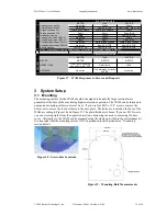
Page 19: ...TOP E STOP RESET IDLE Clear faults power up bus enumerate IDLE Clear faults IDLE ACTIVATE No Action If no warnings or faults ACTIVE No Action REQUEST ERROR Figure 17 WAM Responses to Errors and Requests 3 System Setup 3 1 Mounting The mounting surface for the WAM should be designed to handle the large reaction forces generated at the base of the arm during high acceleration operation The WAM can b...

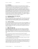
Page 20: ...e PC remotely 3 3 2 Software installation The PC comes with the WAM software loaded You will need to edit etc network interfaces to set an IP address that is compatible with your network We do not recommend using DHCP as we have found that periodic address renegotiation interferes with the real time operation of the WAM The Barrett Technology software library uses syslogd to log all error messages...

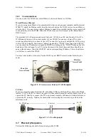
Page 21: ...Document D1001 Version AH 00 21 of 80 Figure 20 Wrist Connector Figure 21 Separating the Outer Link Figure 22 Close up of Outer Link connection Rotate ring this direction to attach Outer Link or Wrist Rotate ring this direction to remove Outer Link or Wrist Alignment Pins D sub connector ...

Page 22: ...ll be on the lower left corner see Figure 23 If a switch is out the raised part of that pin is on the side closest to the edge of the safety board and the opposite is true if the switch is in Table 1 WAM Communication Settings Mode Switch 1 2 Switch 1 3 Ethernet IN IN CAN from External PC OUT OUT Table 2 Hand Communication and Power Settings Modes Switch 2 Switch 1 1 Internal Power Communications ...

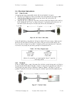
Page 23: ... applications that require alternate DC power sources simply connect the DC power cable directly from the power source to the socket on the WAM labeled DC Power as shown in Figure 26 see Table 3 for details on DC power requirements Tighten the strain relief screws using the screwdriver provided in the maintenance kit Table 3 DC Power Requirements 4 DOF 7 DOF Quiescent 18W Quiescent 27W Typical 28W...

Page 24: ...68 nnn 30 Username is admin password is WAM Once logged in to the AP you can check the IP addresses assigned by DHCP by clicking on the DHCP button on the left hand side of the web page Your PC s network name will be listed there and there should be an entry without a name that is the WAM PC and its corresponding IP address This is the address you will use to control the WAM You may want to add a ...

Page 25: ... rotate them one quarter of a turn clockwise 6 Press Shift Reset Idle on the control pendant 7 Place the WAM into its home position see Appendix C for details on the home position 8 Press Shift Activate on the control pendant The WAM is now ready for use 3 8 Code Examples In the code examples the PC closes a 500 Hz position torque control loop with the WAM over the CAN bus The PC asks the motor co...

Page 26: ...ed to joint torque with zero backlash and near zero friction This makes it possible for the WAM library to perform online real time joint torque calculations using the Jacobian transpose to generate any desired link forces The WAM s gravity compensation routines use this feature to make the robot arm appear weightless by constantly calculating and applying the correct upward force on each link to ...

Page 27: ...ry as your executable application and may be a symbolic link to a configuration file that describes your particular WAM parameters If you add or remove the wrist or change any link or tool masses you will need to edit your active configuration file You should take a look at this file to familiarize yourself with its contents It contains the default home position the Denavit Hartenberg parameters a...

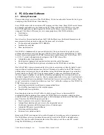
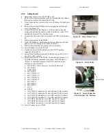
Page 28: ...t http wiki barrett com index php Firmware_update_instructions 4 5 1 Pucks 1 Move to the btutil directory cd btclient src btutil 2 Make the btutil application make clean make 3 Turn on the WAM power supply 4 Press SHIFT RESET IDLE on the control pendant 5 Determine which version of firmware you are upgrading from btutil g 1 6 Note the VERS version and CTS counts parameters 7 Repeat the following s...

Page 29: ...r to the WAM 11 Flip the nearby switch both halves to the OFF position opposite of Figure 32 12 Launch TeraTerm Hyperterminal 9600 baud no parity 8 bits 1 stop bit no flow control 13 Turn on main power to the WAM You should get a prompt Type the following commands in sequence each followed by Enter A mis typed command will NOT result in an error message so type carefully a SET SAFE 4 this is neces...

Page 30: ...o get a single property of a single puck at a time Command setProperty Name Set Property Purpose Sets the properties of Pucks single or group Arguments Bus 0 Node 1 31 0x400 is not valid property 0 108 inclusive use the enumerations in btcan h reply Example Notes The setProperty function in contrast DOES allow nodeIDs OR group messageIDs to be used interchangeably So setProperty 0 0x400 STAT FALSE...

Page 31: ... Saved No Notes Property CMD Definition Execute a special command over CANbus instead of the typical Get Set command Values Units Read Write W Default None Saved No Notes Set CMD to the enumerated value of the desired command Can only be used with commands that don t take values RESET HOME KEEP PASS LOOP HI IC IO TC TO C O T Property DEF Definition Default command for CAN Values Units Read Write W...

Page 32: ...grounded when FET0 1 Pin 34 5V current source Property FET1 Definition Brake output 0 Off 1 On Values Units 0 1 Read Write R W Default 0 Saved No Notes Pin 31 floats when FET1 0 it is grounded when FET1 1 Pin 32 5V current source Property FIND Definition Find command for CAN Values Units Read Write W Default None Saved No Notes Used for calibration Set FIND to the value you want to calibrate setPr...

Page 33: ...es Units 0 2 3 4 5 Read Write R W Default 0 Saved No Notes 0 Idle 2 Torque 3 PID 4 Velocity 5 Trapezoidal Property OTEMP Definition Over temperature limit Values Units Read Write R W Default 82 Saved No Notes MT is reduced gradually 16C before OTEMP When TEMP OTEMP MT will be zero Property PTEMP Definition Peak temperature recorded Values Units Read Write R W Default None Saved Yes Notes Property ...

Page 34: ...o execute the Main firmware Setting STAT 0 forces a firmware reset which will leave the motors free spinning no torque no braking Property TEMP Definition Puck temperature Values Units Read Write R Default Saved No Notes The Puck temperature should not exceed 70 C for extended periods Property THERM Definition Thermistor motor temperature Values Units Read Write R Default Saved No Notes The motor ...

Page 35: ...k is in reset Values Units Read Write R W Default Saved No Notes Property VLOGIC Definition Values Units Read Write R Default Saved No Notes Not yet implemented Property X0 X1 X2 Values Units Read Write R W Default Saved Yes Default N A Notes Property X3 X4 X5 Definition Values Units Read Write R W Default Saved Yes Notes Property X6 X7 Definition Values Units Read Write R W Default Saved Yes Note...

Page 36: ...roperty CTS Definition 32 Bit Counts per revolution Values Units Read Write R W Default 4096 Saved Yes Notes CTS Property DP Definition 32 Bit Default Position Values Units Read Write R W Default 0 Saved Yes Notes Property DS Definition Values Units Read Write R W Default 25000 Saved Yes Notes Property E Definition 32 Bit Endpoint Values Units Read Write R W Default 0 Saved No Notes Property ECMAX...

Page 37: ...LD Definition Flag to hold position after move Values Units Read Write R W Default 0 Saved Yes Notes Property HSG Definition Values Units Read Write R W Default 255 Saved Yes Notes Property IKCOR Definition Current sense correction factor Values Units Read Write R W Default 1638 Saved Yes Notes Property IKI Definition Current sense integral gain Values Units Read Write R W Default 3276 Saved Yes N...

Page 38: ...s simply a non volatile place to store the conversion constant so that the controlling PC can read it upon startup and use it to convert between puck units and SI units of torque for the end user Property IVEL Definition Values Units Read Write R W Default 20 Saved Yes Notes Property JIDX Definition Values Units Read Write R W Default Saved Yes Notes Property KD Definition Values Units Read Write ...

Page 39: ...1500 Saved Yes Notes Property MDS Definition Max Duty Sum for Power Limiting Values Units Read Write R W Default 1650 Saved Yes Notes Property MECH Definition Mechanical encoder angle Values Units Read Write R Default Saved No Notes For magnetic encoders MECH is the raw encoder feedback absolute within one rotation of the motor For optical encoders MECH is the number of encoder counts between the ...

Page 40: ...s Let s say MT 750 TL1 2500 TL2 4000 You send a T of 2800 The safety system is okay with this it just shows the warning light on the pendant The puck notices that abs 2800 exceeds 750 so it sets its own torque output to 750 sign 2800 Property MV Definition Maximum Velocity in counts millisecond Values Units Read Write R W Default 1500 Saved Yes Notes Property OD Definition Values Units Read Write ...

Page 41: ...y the last received torque until a new torque is sent or the MODE changes to MODE_IDLE Property TENSO Definition Values Units Read Write R W Default Saved Yes Notes Property TENST Definition Values Units Read Write R W Default Saved Yes Notes Property TIE Definition Flag to tie inner and outer links Values Units Read Write R W Default 0 Saved Yes Notes Property TSTOP Definition Time until consider...

Page 42: ...s tied together Property IFAULT Definition If IFAULT is greater than 0 and a fault is observed by the safety system IFAULT is decremented by one and the fault is ignored Values Units 0 to 20 typical Read Write Default 0 Saved Notes To set the initial positions of the pucks you must also set IFAULT Ignore Fault at that time to prevent the giant instantaneous position change from causing an over vel...

Page 43: ...t to set these properties directly using SetProperty please note that they are in Q4 12 notation so take whatever you want the value to be and multiply it by 4096 before you set it Q4 12 means 4 bits of integer 12 bits of fraction 0x1000 1 0 0x1800 1 5 0x7800 7 5 If you go much higher you ll go negative do not do this See the source code for SetSafetyLimits in src btwam btwam c for an example Prop...

Page 44: ...r sending the pucks their known initial position set the safety system s ZERO property to 1 so it can start calculating Cartesian velocities Values Units Read Write Default Saved Notes Use the DefineWAMpos function in src btwam btwam c to set the initial positions of the other motor controllers This is called automatically during the normal OpenWAM call ...

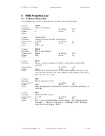
Page 45: ...T 100 LCVC 9 TEMP 55 OT2 10 PTEMP 56 CT 11 OTEMP 57 CT2 12 BAUD 58 M 13 LOCK 59 M2 14 DIG0 60 DS 15 DIG1 61 MOFST 16 FET0 62 IOFST 17 FET1 63 UPSECS 18 ANA0 64 OD 19 ANA1 65 MDS 20 THERM 66 MECH 21 VBUS 67 MECH2 22 IMOTOR 68 CTS 23 VLOGIC 69 CTS2 24 ILOGIC 70 PIDX 25 SG 71 HSG 26 GRPA 72 LSG 27 GRPB 73 IVEL 28 GRPC 74 IOFF 29 CMD 75 IOFF2 30 SAVE 76 MPE 31 LOAD 77 EN 32 DEF 78 TSTOP 33 FIND 79 KP ...

Page 46: ...frame 47μS plus payload data 3 bytes 24μS typ CANbus transceivers are not rated above 1 Mbps due to slew rate limitations 7 3 ID Specifications 7 3 1 Message IDs GFFFFFTTTTT 11 bits binary G Group 0 Directed message 1 Group broadcast F From ID Host 00000 Motor N N T To ID or group Examples 00000000011 Directed message from host to motor 3 3 00011 binary 10001100100 Group broadcast from motor 3 to ...

Page 47: ...h byte of data value H High byte of data value The CAN frame data length code DLC is set to the number of bytes being transmitted 7 4 2 Exceptions 1 The Position property P is a 22 bit 2 s complement number It is packed into a 3 byte frame payload 00MMMMMM mmmmmmmm LLLLLLLL It is always sent to Group 3 2 Command torque can be sent as a set of four 14 bit 2 s complement numbers It is sent to the mo...

Page 48: ...s the motors to apply any torque sent to them When MODE MODE_IDLE motors will ignore any torque commands sent and apply braking When using a WAM the safety system will set the MODE when you press the IDLE ACTIVATE buttons Do not try to bypass the WAM s safety system by setting the MODE directly this will cause undesired operation Host sends MsgID 10000000000 Group 0 Data 00110000 Get property 48 P...

Page 49: ...2 Jul 29 20 27 45 WAM WAM getBusStatus status 10 2 Jul 29 20 27 45 WAM WAM Puck ID 1 CTS 4096 IPNM 2700 00 PIDX 0 GRPB 1 Jul 29 20 27 45 WAM WAM Puck ID 2 CTS 4096 IPNM 2562 00 PIDX 1 GRPB 1 Jul 29 20 27 45 WAM WAM Puck ID 3 CTS 4096 IPNM 2562 00 PIDX 2 GRPB 1 Jul 29 20 27 45 WAM WAM Puck ID 4 CTS 4096 IPNM 2700 00 PIDX 3 GRPB 1 Jul 29 20 27 45 WAM WAM Puck ID 5 CTS 4096 IPNM 4961 00 PIDX 0 GRPB 2...

Page 50: ...ta or errors from within the WAM control loop Boot from a bootable CD like sysresccd org and delete the syslog files or other files to make some room 3 The network connection is not active logging in over the network Solution s a Make sure the Ethernet cable is plugged into the PC b Make sure your DHCP server is active if using DHCP c Check that the Ethernet driver is loaded from local terminal ls...

Page 51: ... 2 There is some other electrical problem Solution s a Contact Barrett for repair Problem Some joints have resistive braking some do not The angles that btdiag returns for the joints without resistive braking are incorrect This is easiest to check for at the home position Reason s 1 The Pucks without resistive braking are not powering up correctly NOTE It is normal to have no resistive braking in ...

Page 52: ...unique ID If the Pucks are not enumerating correctly disconnect them from the CANbus on by one until you find the one causing the conflict Use btutil to set a new Puck ID for that puck 3 Grounding problem Solution s a Eliminate CANbus ground loops The CANbus shield is connected to Earth ground on the Safety Board If your PC is also grounded you should use an opto isolated CANbus card to prevent gr...

Page 53: ... about a 50 chance of working itself out eventually 2 Loose ball bearing retainer Solution s a Eliminated in newer designs usually does not interfere with operation except for clicking noise 3 Insufficient motor shaft axial preload shimming the rotor shaft should not be able to move axially inside the motor Solution s a Return to Barrett for repair Problem The robot fails to follow scaled trajecto...

Page 54: ...s Barrett is working on calibration software and will notify the WAM User List when it is released Problem Safety Board is randomly rebooting The pendants reinitialize themselves Reason s 1 There are electrical noise spikes dips in the power circuitry of the Safety Board Solution s a Contact Barrett for a replacement board Problem Pendant lights do not come on specifically the IDLE light but Pucks...

Page 55: ...rength of the steel cables Increasing these values increases the likelihood of cable failure 3 The simple PID control that ships with the example code is not robust enough to handle loads offset significantly from the tool center point or loads with unusual inertial characteristics Solution s a Design a more robust control method for your application Problem WAM will not enter Idle mode the WAM st...

Page 56: ...x a CAN communications card a CANbus cable Figure 33 shows a schematic of the WAM system subcomponents that are important to the WAM programmer The power supply is used with AC outlets as specified in Section 3 6 1 It provides 48 VDC to the safety module which in turn provides the necessary voltage to the motors and the internal PC The internal computer is responsible for closing the control loop ...

Page 57: ...y states see Section 2 for details The safety module will shut down the WAM and cause the motors to resistively brake if it senses a dangerous situation see Section 2 2 Barrett Technology has created specially designed motor controllers called Pucks which are mounted directly to the motors they control A Puck serves as a power source for the motors and commands a smooth continuous torque based on ...

Page 58: ...ry robotics books available We recommend Spong M Hutchinson S Vidyasagar M Robot Modeling and Control 2006 John Wiley Sons as we use the variant of the Denavit Hartenberg D H method that is from this book to establish the coordinate frames Figure 35 WAM 4 DOF dimensions and D H frames Figure 35 shows the 4 DOF WAM system in the zero position A positive joint motion is based on the right hand rule ...

Page 59: ...9 of 80 Figure 36 WAM 7 DOF dimensions and D H frames Figure 36 shows the entire 7 DOF WAM system in the zero position A positive joint motion is based on the right hand rule for each axis Figure 37 through Figure 43 on the following pages show explicitly each of the seven joint kinematic parameters and joint limits ...

Page 60: ...rm User s Manual support barrett com www barrett com 2008 Barrett Technology Inc Document D1001 Version AH 00 60 of 80 Figure 37 WAM Arm Joint 1 Frames and Limits Figure 38 WAM Arm Joint 2 Frames and Limits ...

Page 61: ...rm User s Manual support barrett com www barrett com 2008 Barrett Technology Inc Document D1001 Version AH 00 61 of 80 Figure 39 WAM Arm Joint 3 Frames and Limits Figure 40 WAM Arm Joint 4 Frames and Limits ...

Page 62: ...nual support barrett com www barrett com 2008 Barrett Technology Inc Document D1001 Version AH 00 62 of 80 Figure 41 WAM Arm Joint 5 Frames and Limits Figure 42 WAM Arm Joint 6 Frames and Limits 1 24rad 71o 4 76rad 273o ...

Page 63: ...WAM Arm User s Manual support barrett com www barrett com 2008 Barrett Technology Inc Document D1001 Version AH 00 63 of 80 Figure 43 WAM Arm Joint 7 Frames and Limits ...

Page 64: ... Table 5 7 DOF WAM frame parameters i ai αi di θi i ai αi di θi 1 0 π 2 0 θ1 1 0 π 2 0 θ1 2 0 π 2 0 θ2 2 0 π 2 0 θ2 3 0 045 π 2 0 55 θ3 3 0 045 π 2 0 55 θ3 4 0 045 π 2 0 θ4 4 0 045 π 2 0 θ4 Τ 0 0 0 35 5 0 π 2 0 3 θ5 6 0 π 2 0 θ6 Notes Units of meters and radians 7 0 0 0 06 θ7 T Tool frame Τ 0 0 0 For example to generate the transform from coordinate Frame 2 to coordinate Frame 1 i e the position a...

Page 65: ... z z y y y y x x x x Tool p w v u p w v u p w v u Equation 3 Tool frame matrix You define the Tool Τ 4 frame for your specific end effector The forward kinematics are determined for any frame on the robot by mulitplying all of the transforms up to and including the final frame To determine the tool end tip location and orientation use the following equation Tool Tool Τ Τ Τ Τ Τ Τ 4 4 3 3 2 2 1 1 0 ...

Page 66: ... 80 9 2 2 4 DOF with Gimbals A 4 DOF WAM Arm can be outfitted with optional 3 axis non motorized gimbals that give precise angular feedback The kinematics of the first 4 joints is identical to a 4 DOF WAM Arm The kinematics for the additional 3 axes is shown in Figure 44 Figure 44 Denavit Hartenberg Frames 4 DOF Gimbals ...

Page 67: ...AM Gimbals in the zero position A positive joint motion is based on the right hand rule for each axis The D H parameters that were derived from Figure 44 are located in Table 7 below Table 7 4 DOF WAM Gimbals DH Parameters i ai αi di θi 1 0 π 2 0 θ1 2 0 π 2 0 θ2 3 0 045 π 2 0 55 θ3 4 0 4 π 2 0 θ4 5 0 π 2 0 θ5 π 2 6 0 π 2 0 155 θ6 π 2 7 0 0 0 θ7 ...

Page 68: ...14 93 6 n 1 4 3 2 1 4 2 3 2 3 2 2 1 4 3 2 1 1 0 0 0 0 2 2 0 0 2 1 2 1 0 0 0 0 1 θ θ θ θ θ θ θ θ M M M M N N n N n N N N J J J J Equation 6 WAM Motor to Joint position transformations 7 6 5 7 5 6 5 6 5 5 7 6 5 1 0 0 0 2 2 0 2 1 2 1 θ θ θ θ θ θ M M M N N n N n N N J J J Equation 7 Wrist Motor to Joint position transformations The motor position can also be derived from joint space by taking the inve...

Page 69: ... N J J J J Equation 10 Arm Motor to Joint torque transformation 7 6 5 7 6 5 6 5 5 5 7 6 5 0 0 0 0 τ τ τ τ τ τ M M M N n N n N N N J J J Equation 11 Wrist Motor to Joint transformations The following equations determine motor torque from the joint torque 4 3 2 1 4 2 3 2 2 3 2 1 4 3 2 1 1 0 0 0 0 2 2 1 0 0 2 2 1 0 0 0 0 1 τ τ τ τ τ τ τ τ J J J J N N n N N n N N M M M M Equation 12 Arm Joint to Motor...

Page 70: ...Attach a standard serial cable from COM port to rear of Hand Power Supply Box The Hand is attached and ready for operation Read the BarrettHand User Manual before proceeding with Hand operation Before operating both Hand and Arm together the Hand should be tested on the end of the Arm Place Arm in a configuration that allows the Hand to move through its full range of motion Follow the procedures i...

Page 71: ...3 2 0 113 3 2 8 157 2 8 157 4 3 1 180 0 9 50 5 1 24 71 4 76 273 6 1 57 90 1 57 90 7 3 0 172 3 0 172 Weight 4 DOF WAM 25 6 kg 56 5 lb 7 DOF WAM 27 4 kg 60 5 lb Maximum Payload 4 DOF WAM 4 0 kg 8 8 lb at endpoint 7 DOF WAM 3 0 kg 6 6 lb at endpoint Motor Type Neodymium Iron Boron brushless DC servo motors Mechanisms Cable drives integrated with a cable differential Barrett quick connect feature for ...

Page 72: ...ional External Hand control cable optional Available Options 3 DOF Wrist 3 DOF Gimbals External Computer WAM Dimensions NOTE The dimensions for a 4 degree of freedom WAM are the same except that the 4 degree of freedom WAM does not have a joint at 850 mm and the End Plate dimension is 900 mm All measurements are in millimeters Figure 45 WAM Dimensions 900 to End Plate for 4 axis WAM 910 to End Pla...

Page 73: ...08 Barrett Technology Inc Document D1001 Version AH 00 73 of 80 Figure 46 Tool Plate Dimensions US Patents and international equivalents 4 903 536 4 957 320 5 046 375 5 207 114 5 388 480 5 501 498 D351 849 D352 050 Additional US and international patents pending ...

Page 74: ...de mostly from aircraft grade aluminum but also contains some steel ball bearings stainless drive cables fasteners carbon fiber epoxy internal structures titanium Ti 6Al 4V PEEK copper motor stator coils and bus signal wiring cobalt motor laminations ceramic rotor magnets Teflon impregnated ceramics for cable pulley surfaces Kydex acrylic polyvinyl chloride covers RTV FR4 phenolic adhesives beryll...

Page 75: ... is the raw magnetic encoder feedback absolute within one rotation of the motor MOFST Optical Encoders MOFST is the distance in encoder counts between the index pulse of the encoder and the start of an electrical cycle for that motor a point where the magnets are aligned with a single phase coil Magnetic Encoders MOFST is the encoder reading at the start of an electrical cycle Q5 How do I calculat...

Page 76: ...inding currents for that position that will produce either a desired trajectory or a desired torque in cases with very low Coulomb friction Then in most modern motor controllers a set of PWM signals is generated that control a set of typically 6 FETs through charge pumps arranged in a double H bridge in the 6 FET case 2 A high level motion controller coordinates the motions of one or more axes of ...

Page 77: ...atics relative orientation of the gravity vector and instantaneous pose must be known or knowable The link and payload masses must be known a priori or measured in a process called identification In these circumstances only a few sines and cosines must be evaluated to determine the unique set of joint torques required to balance gravity precisely and these balancing torque change only gradually as...

Page 78: ...oder Developed over several years by Barrett Technology this puck weighs only 44gms and is only 35mm dia x 17 high with connectors The Puck fulfills both definitions of a Controller see Controller Stiffness The stiffness of a spring or similar mechanism with units of force distance or force x distance in the case of trosional mechanisms is defined as the slope of the curve of the restoring force r...

Page 79: ...ne Cord 11 15 23 CAN Cable 15 24 DC Power Cable 11 DC Power Cord 23 Ethernet Cable 11 24 Pendant Cables 11 23 Electronic Architecture 56 57 Encoders 75 77 F FAQ 74 75 Firmware 11 77 Upgrades 16 G Gimbals 14 Gravity Compensation 28 77 H Haptics 77 Haptic Devices 77 Haptic Objects 77 Home Position 27 77 J Jacobian 77 Inverse 78 Transpose 78 K Kinematics 58 69 71 78 M Maintenance Kits WAM 11 12 Wrist...

Page 80: ...1 Version AH 00 80 of 80 Support Reference Sheet 16 Support Subscription 16 T Troubleshooting Cables 53 Gravity Compensation 53 Joints 51 53 54 Pendants 54 55 Power Supply 53 Pucks 54 Safety Board 54 Trajectories 53 54 Updates 52 Troubleshooting 52 V Voltage 10 56 71 W WAM 7 78 Weight 71 Wrist 13 20 ...

Reviews: