WAM Arm – User’s Manual
support@barrett.com
www.barrett.com
© 2008 Barrett Technology®, Inc.
Document: D1001, Version: AH.00
20 of 80
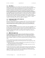
3.2 Grounding
Grounding of all hardware must be considered when locating the WAM and its peripherals.
Multiple grounding paths between the external power supply, the WAM chassis, the Barrett Hand
power supply, an external computer and earth ground can cause internal communications
problems. It is important to mount the WAM itself on a non-grounded surface. However, if you
need to physically mount it to a grounded structure (upside-down to a grounded I-Beam, or
mounted to a grounded metal table, for example) contact Barrett Technology for instructions on
making a slight modification to the external wiring to avoid multiple ground paths. Additionally, it
is preferable that the metal chassis of the External Power Supply, the metal chassis of the Barrett
Hand Supply (if applicable) and the WAM chassis are not in electrical contact with each other. If
this is not possible, contact Barrett Technology for instructions. Finally, if using an external
computer connected to either the WAM through the CANBus or the external Barrett Hand Supply,
the computer
should
be grounded. Again, contact Barrett if this poses a problem. A computer
connected to the Ethernet port can either be grounded or not grounded.
3.3 Installing the External PC (Optional)
3.3.1 Physical
Installation
Install the PC shipped with the WAM as you would any other PC. The CANbus cable connects to
the lower port of the PCI CAN card, not the built-in serial port. You will need to add a monitor
while performing initial setup of the PC. Afterwards, you may use the PC for development or
remove the monitor and use remote terminal software (such as
ssh
) to operate the PC remotely.
3.3.2 Software
installation
The PC comes with the WAM software loaded. You will need to edit /etc/network/interfaces to set
an IP address that is compatible with your network. We do not recommend using DHCP, as we
have found that periodic address renegotiation interferes with the real-time operation of the WAM.
The Barrett Technology software library uses
syslogd
to log all error messages to a file. It is
highly recommended to make sure that
syslogd
is running. Error messages may be found in the
/var/log/syslog
text file.
3.4 WAM Wrist (Optional)
To avoid damaging the WAM electronics, please make sure the WAM is powered off before
detaching or attaching any outer link. In addition, if the Wrist was shipped separately from the
WAM, a Safety Termination will be attached to the base connector of the Wrist, and must be
removed before mounting the Wrist. If the Wrist is ever removed from the WAM, ensure that the
Safety Termination is attached as soon as the Wrist is disconnected to prevent damage to the Wrist
Pucks.
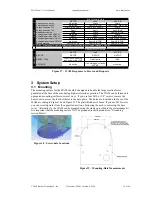
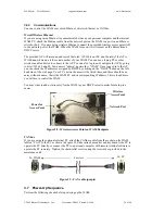
Figure 21 shows that the outer link can be unscrewed and removed from the WAM to
accommodate the WAM Wrist (if the 7-DOF WAM is purchased). After removing the outer link,
connect the WAM Wrist:
1.Align the D-sub connector of the Wrist with the mating connector on the end of the “elbow” of
the WAM such that both have the same orientation.
2.Connect the alignment pins on the end of the elbow with the mating connections on the Wrist.
3.Thread the quick-connect ring onto the wrist base.
No special wrenches, fasteners, or tools are required, however, it may be necessary to shake the
outer link (or Wrist) gently back and forth while tightening or loosening the ring. This ring should
only be hand-tightened. It is normal for there to be a small number of threads left when fully
tightened. This single operation also makes all electrical connections to the WAM Wrist. Figure
20 shows the electrical connector at the end of the WAM.


