Lindsay Transportation Solutions Sales and Services, Inc
(888) 800-3691 [U.S. toll free] or +1 (707) 374-6800
Lindsay Transportation Solutions Sales and Services, Inc
(888) 800-3691 [U.S. toll free] or +1 (707) 374-6800
10
Step 2 – Installing Posts 6- 2
Begin installing posts 2 – 6 at standard highway
post spacing, 75” (1905mm) and post height, 28
1/4” (720mm) or 31 3/4” (805mm) depending on the
height of the system being installed.
Please note: Post 1 consists of two parts, Post 1
Top and Post 1 Bottom. Post 1 Top is different for
27 ¾” systems vs 31” systems . Ensure that the
correct Post 1 Top is installed for the appropriate
height system. Post 1 Top is not interchangeable
between 27 ¾” and 31” height systems.
All posts should be the same height from
ground level throughout the entire system.
Posts #6 to #3 are either standard “I” beam
posts
OR
timber CRT posts. Post 2 is either the
Special “I” beam post or a timber CRT (see parts
identification photo).
Posts may be directly driven, or in stiff soils a
150mm (6 in) diameter hole drilled, and the post
then driven into the hole. The post may also be
placed in an oversized augured hole but care
must be taken to ensure the backfill is properly
compacted.
Hint:
Offset Post 3 back from the string line 40-
50mm (up to 2 in) to make it easier to push rail 1
and Slider Panel over rail 2.
When driving steel posts, ensure that a driving
cap with timber or plastic insert is used to prevent
damage to the galvanizing on the top of the posts.
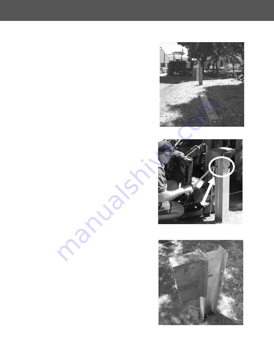
Ensure that Post 2 has the post bolt
holes
on the
side nearest the rail
Notches go to the backside as shown and are
only used on the median application.
(Figure 2)
Bolt the blockout to the post at post 3, prior to
attaching to the rail (Figure 3).
Figure 1. Pull a string line with the desired offset.
Figure 2. Holes on straight rail side, notches on
the backside.
Figure 3. Bolt the blockout to post 3 prior to
attaching the rail.
X-Tension - Tangent Installation Instructions
INSTALLATION AND MAINTENANCE MANUAL


