Lindsay Transportation Solutions Sales and Services, Inc
(888) 800-3691 [U.S. toll free] or +1 (707) 374-6800
Lindsay Transportation Solutions Sales and Services, Inc
(888) 800-3691 [U.S. toll free] or +1 (707) 374-6800
14
INsTALLATIoN ANd MAINTENANCE MANUAL
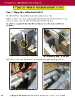
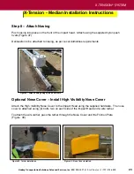
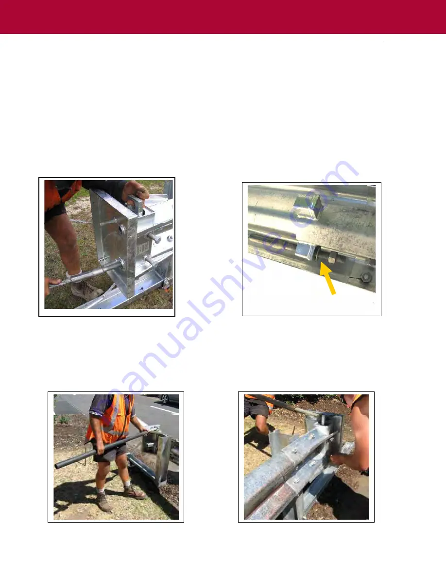
Figure 23. Use crow bar to turn Friction Plate.
Figure 24. Use socket to lock bar in the turned position.
Page 14
Step 11 – Installing the Cables
Install the
Friction Plate in the top of the Impact Head, adjustment hole up. Take the cable closest to the
road, pick up the downstream cable fitting and walk to the head, passing the cable through the
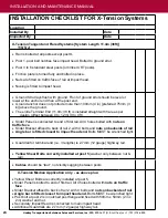
bottom hole, through the Friction Plate (Figure 21) and out the backside of the Impact Head.
Now thread
the cable down the backside of the rail following the bottom trough of the W-beam and attach to
the bottom “box” on the Cable Bracket at post 7. Repeat this process with the other cable but
push it through the top hole and thread it along the top trough of the W-beam.
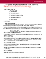
Place the nuts and washer on the cables at the Cable Bracket end but only run them a few turns (Figure
22).
Do not tighten cables at this stage (or the Friction Plate will not turn)
Figure 21. Pass the cable through the bottom hole.
Figure 22. Do not tighten nuts at this time.
Step 12 – Turning the Friction Plate
Put a crow bar through the hole at the top of the friction plate (Figure 23) and turn it to the final
position.
Using a socket, tighten the 4 - M20 x 75mm (3/4 in x 3 in) bolts on the side of the impact
head to lock the bar in the turned position (Figure 24).


