Electrical Connections
All electrical connections should be made inside
the J-box. Make electrical connections as follows:
Note:
Cap unused leads to prevent shorting.
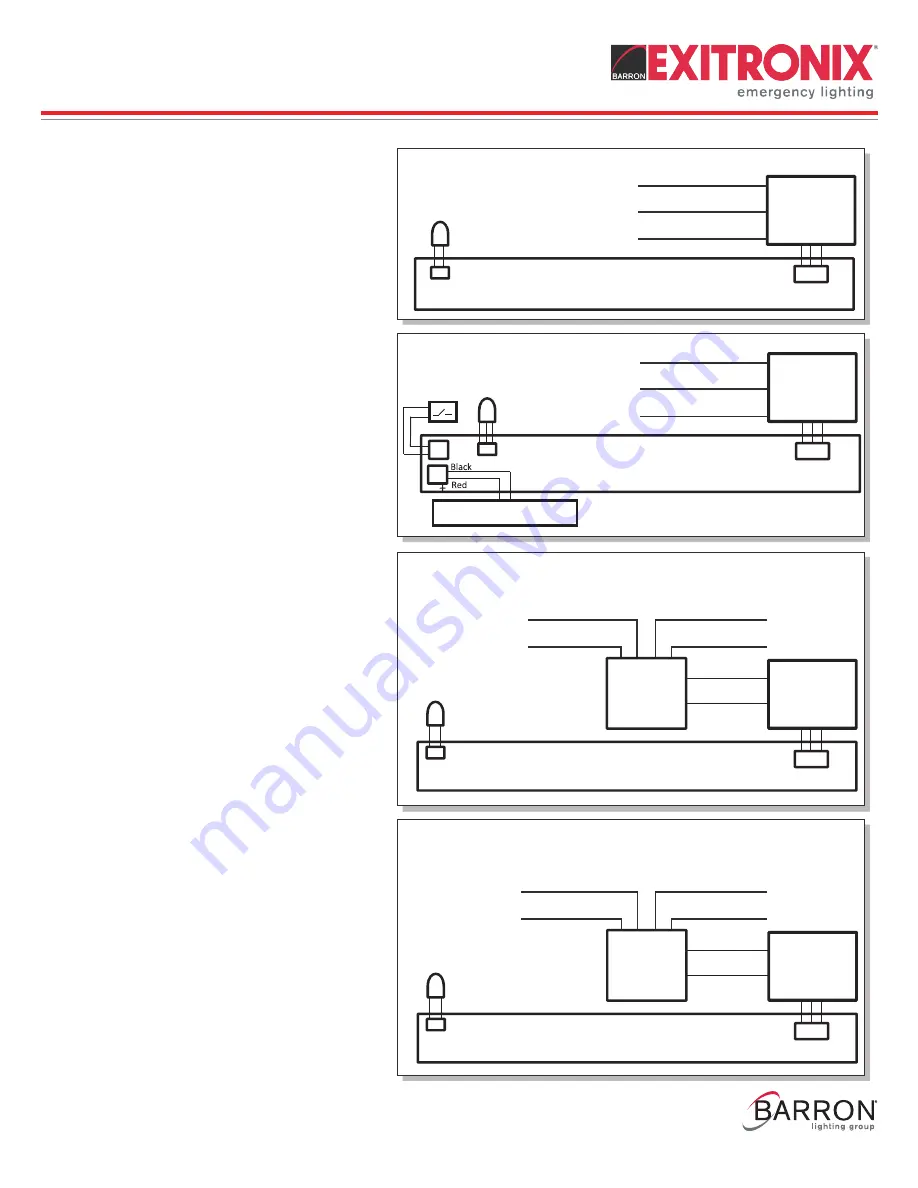
AC Only or With Battery Models (Fig. 4 and 5)
120 or 277VAC
White - Common
Black - 120VAC
Red - 277VAC
Two Circuit Input (2CI) Models (Fig. 6 and 7)
2CI option models
have two inputs, one for the
AC input and the other for the auxiliary input.
Please make connections as follows:
120 or 277VAC Line Auxiliary Line
White - Common
Gray - Common
Black - 120VAC
Yellow - 120 or 277VAC
Orange - 277VAC
Note:
The AC and auxiliary power cannot be
simultaneously live, consult factory for a
solution.
Fig. 4 - AC Only
Fig. 5 - With Battery
Fig. 6 - 2CI with 120VAC Input
Fig. 7 - 2CI with 277VAC Input
Red (277VAC)
Black (120VAC)
White (Com)
LED
Indicator
PCB/LED Board
Transformer
Red (277VAC)
Black (120VAC)
White (Com)
Transformer
LED
Indicator
Magnetic
Test Switch
Battery
LED
Indicator
2CI1 Relay
Generator/UPS
Yellow (120VAC)
Gray (Com)
Utility Power
Black (120VAC)
White (Com)
Transformer
PCB/LED Board
LED
Indicator
2CI7 Relay
Generator/UPS
Yellow (277VAC)
Gray (Com)
Utility Power
Orange (277VAC)
White (Com)
Transformer
PCB/LED Board
PCB/LED Board
NXFX Series
Installation Instructions
10070226
R
EV 1 - 08/20
5
800-533-3948 www.barronltg.com


