RDG603A31- Issue 4
Page 22 of 88
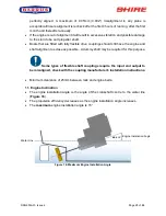
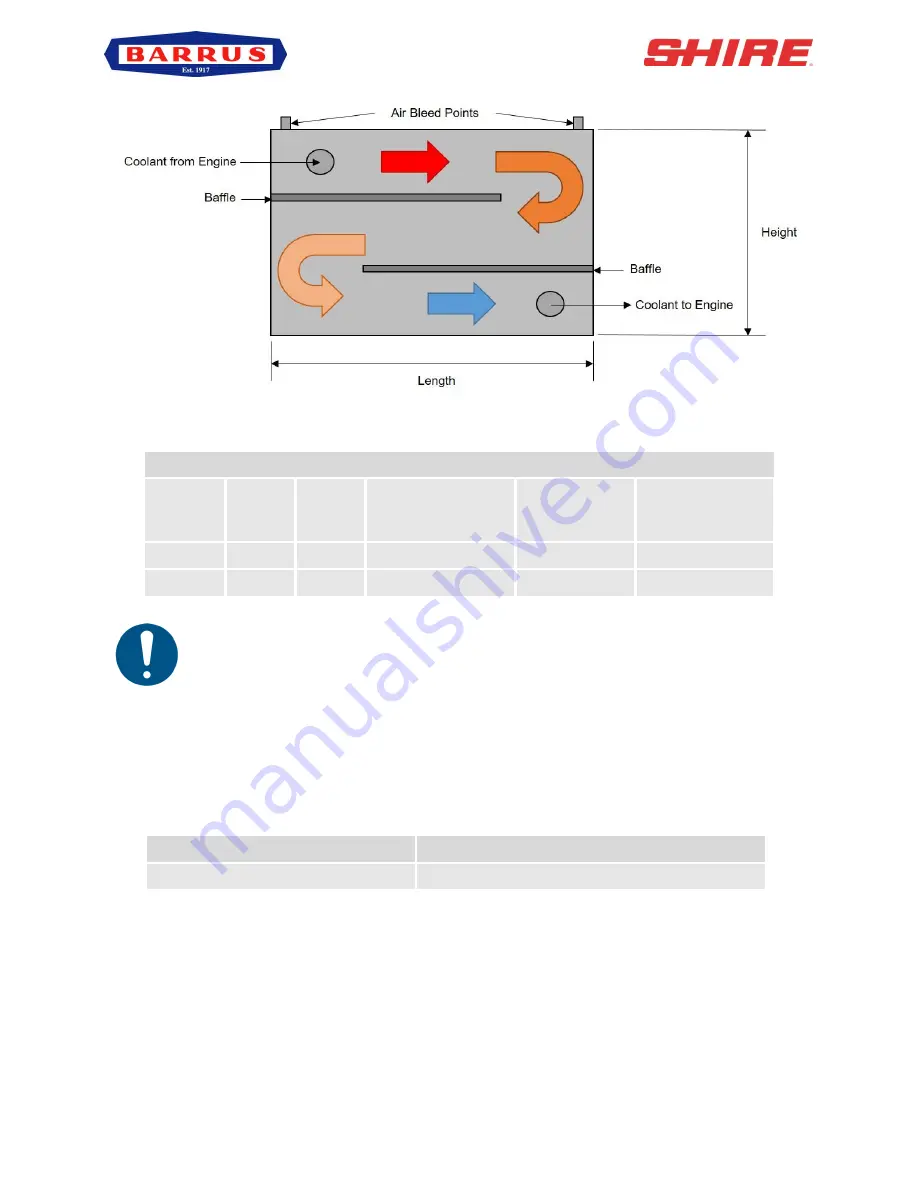
Figure 10: Skin Tank Flow Diagram
Recommended Skin Tank Size
Engine
HP
KW
Skin tank
surface area m
2
Suggested
Height mm
Suggested
Length mm
60
60
44
1.35
750
1800
65
65
48
1.46
750
1950
If a hydraulic bow thruster is used, the skin tank size must be increased by up
to approx 10% or a separate skin tank installed to cool the hydraulic oil. Please refer
to Section 5
– Installation, 21. Hydraulic Drive Transmission for further information.
5. Engine Cooling Water Inlet and Outlet Hose Connections
These are on the left hand (port) side of the engine:
Engine
Size (mm)
Shire 60, 65
35mm OD, inlet and 35mm OD, Outlet
Use a good quality hose that cannot collapse or kink and is capable of working at temperature
in excess of 100°c.
A.S.A.P. Supplies LTD can supply suitable 28mm ID hoses if the correct size hoses cannot
be sourced locally. The part numbers used by A.S.A.P. Supplies LTD are shown in the
following table.


