RDG603A23
–
Issue 20
Page 20 of 84
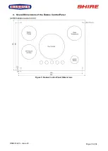
4. Overall Dimensions of the Deluxe Control Panel
(All Dimensions are in mm)
Figure 5: Deluxe Control Panel Dimensions
Page 1: ...603A23 Issue 20 CANAL ENGINE MANUAL For the following engine model Shire 90 Standard Model there may be a number of optional extras or alternative components that might be fitted to an engine that are...
Page 2: ...rt symbol appears throughout the manual It means attention be alert as your safety is involved Please read and follow the message that appears after the safety alert symbol NOTICE This indicates a sit...
Page 3: ...nquiry or when ordering spare parts Information about the engine serial number and its location on the engine can be found in SECTION 2 of the manual Shire Engine Manuals and Shire Parts Books To acce...
Page 4: ...e yourself with the engine and its parts before operation The PRM Gearbox Manual is also available from the PRM website www prm newage com If the engine is fitted with an E Kit and or Hybrid options p...
Page 5: ...allow for installation and commissioning following this the warranty period will automatically start The repair or replacement of parts or the performance of service under this warranty does not exte...
Page 6: ...se engine fuel injection system damage which is not covered by the warranty The fuel system should be fully primed ahead of engine starting failure to do so can cause damage to the engine starting sys...
Page 7: ...not consistent with the requirements laid out Systems using or affected by an accessory or part not manufactured or sold by EP Barrus Ltd Systems that have been altered or modified including addition...
Page 8: ...e maintained for a minimum of 15 minutes TRANSFER OF WARRANTY The warranty is valid for the first owner of the Shire engine and is transferrable only at the discretion of EP Barrus Ltd River Canal Res...
Page 9: ...Panel 17 2 Control Panel Overview 17 3 Warning Light Procedure 17 4 Overall Dimensions of the Deluxe Control Panel 20 SECTION 5 Installation 21 1 Ventilation 21 2 Engine Beds 21 3 Cooling System 21 4...
Page 10: ...38 4 Full Load Running 38 5 Refuelling 38 6 Diesel Fuel Additive 39 7 Exhaust Back Pressure 39 8 Hybrid System For engine with Hybrid System fitted 39 9 Single Shift Control Lever Side Mount Operation...
Page 11: ...ler List 57 SECTION 12 Shire Parts 59 SECTION 13 Afterlife Recycling 61 SECTION 14 Declarations 62 1 Declaration of Conformity for Recreational Craft Propulsion Engine with the requirements of Directi...
Page 12: ...before carrying out any maintenance or repairs 2 Lifting DANGER CRUSH HAZARD NEVER STAND UNDER A HOISTED ENGINE IF THE HOIST MECHANISM FAILS THE ENGINE WILL FALL ON YOU CAUSING SERIOUS INJURY OR DEAT...
Page 13: ...ZARD WAIT UNTIL THE EXHAUST COOLS BEFORE YOU TOUCH IT Exhaust gases may have temperatures as high as 650 C and contain elements which are harmful if ingested It is therefore essential that exhaust sys...
Page 14: ...away from the battery NO SMOKING Batteries contain sulphuric acid if splashed on skin or eyes flush well with water and seek medical advice Keep battery tops and battery compartment ventilated at all...
Page 15: ...s Abbreviation Type of Engine Description CB Canal Boat Keel cooled dry exhaust manifold WB Work Boat Seawater Heat Exchanger cooled dry exhaust manifold with either a dry exhaust system same as a Can...
Page 16: ...Shire 90 Right Side Viewed from rear Note There are a number of other optional extras that may be fitted to an engine that are not shown here Description 1 120 Amp 12 Volt Alternator 2 150 Amp 12 Vol...
Page 17: ...ire 90 Deluxe Control Panel Panel supplied as standard On certain engines a different control panel may be supplied as an option 3 Warning Light Procedure When the ignition is first turned on the cont...
Page 18: ...first turned on for 5 8 seconds to indicate the heating system is operational When the light goes out the engine can be started Whilst the control panel is in operation all the gauges are backlit Thi...
Page 19: ...ine immediately Contact your local dealer Failure to stop the engine may result in permanent engine damage 5 150A Alternator Charge Warning Light This indicates that the alternator has stopped chargin...
Page 20: ...RDG603A23 Issue 20 Page 20 of 84 4 Overall Dimensions of the Deluxe Control Panel All Dimensions are in mm Figure 5 Deluxe Control Panel Dimensions...
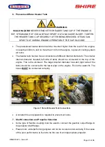
Page 21: ...oling System Ensure pipe work to and from the skin tanks is of sufficient bore Ensure tight bends and elbows are avoided or kept to a minimum sizes are listed overleaf For a Shire 90 45mm 1 is the min...
Page 22: ...eparate skin tank installed to cool the hydraulic oil if a hydraulic bow thruster is used Please refer to Section 5 Installation 21 Hydraulic Drive Transmission for further information 5 Engine Coolin...
Page 23: ...t internal diameter s The smaller internal diameter hosetail left side of tank should be connected to the top of the engine This is the air bleed The larger internal diameter hose tail right side of t...
Page 24: ...before shaft alignment is checked to allow the mounts time to settle under the engine weight Ensure that the anti vibration mount centre screw is sufficiently raised so as not to touch the engine bed...
Page 25: ...RDG603A23 Issue 20 Page 25 of 84 Figure 8 Correct Anti Vibration Mount Installation...
Page 26: ...26 of 84 Figure 9 Correct Anti Vibration Mount Installation Description 1 Normal mounting position 2 Alternative mounting position if engine compartment space is restricted Figure 10 Anti Vibration Mo...
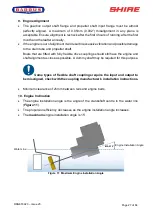
Page 27: ...fully flexible drive couplings should still have the engine and shaft alignment as close as possible A dummy shaft may be required for this purpose Some types of flexible shaft couplings require the i...
Page 28: ...nator charges the start battery The blue link wire between the 120A Alternator B terminal or 150A B terminal and the starter motor solenoid MUST be removed when the domestic battery is connected Both...
Page 29: ...irt and water A separate water trap must be fitted to all engine installations The engines are supplied with an additional fuel pre filter water trap as standard Connect fuel feed return hoses from en...
Page 30: ...HAZARD WAIT UNTIL THE ENGINE COOLS BEFORE YOU DRAIN THE ENGINE COOLANT HOT ENGINE COOLANT MAY SPLASH AND BURN YOU John Deere recommend that Cool Gard is used Cool Gard is already mixed and must NOT ha...
Page 31: ...sitively and that the drive direction corresponds with the gearshift control lever Ensure that the gearbox control lever and the gearshift lever are both in neutral before connection Adjust if necessa...
Page 32: ...ternator 3 x 150 450 ampere hour maximum battery bank size Example 2 Weekend cruising or hire fleet application fitted with a 240amp domestic alternator 3 5 x 240 840 ampere hour maximum battery bank...
Page 33: ...table This must be set to the alternator with blue and black wire connected to it Confirm settings to tacho meter reader An optical tachometer is required to check the reading Barrus Alternator Amps...
Page 34: ...ve transmissions generate far more heat than a conventional marine gearbox Therefore the size of the oil cooler installed must be calculated by the hydraulic drive transmission supplier This is to ens...
Page 35: ...M 280 with power take off is designed for driving hydraulic pumps made to SAEJ77 Series B specification The maximum power which can be transmitted is 22kW 29 5hp per 1000rpm The power take off operate...
Page 36: ...ratio of antifreeze to water All air has been bled from skin tank calorifier and pipework Engine and gearbox oil levels are as specified Throttle and gear cables correctly adjusted and operating smoot...
Page 37: ...losed Ensure the gearshift control level is set to neutral and that all persons are clear of any moving parts Insert ignition key Turn key to on position Observe warning lights and gauges on deluxe pa...
Page 38: ...carbon and condensation enhancing engine life and reducing emissions Running the engine at or near maximum speed whilst in gear may not be possible on inland waterways with speed limits in place If th...
Page 39: ...ives will ensure that your engine fuel injection system is in top condition which should result in many years of smooth reliable operation without the cost and inconvenience of expensive breakdowns du...
Page 40: ...er Side Mount Operation Optional RDG9210055 To engage forward or reverse gear Lift the safety latch under the handle before shifting To rev the engine in neutral Pull the lever out sideways from the m...
Page 41: ...ntainer Operate the pump handle to empty the sump Note Remember to refit the blanking plug afterwards Place a drip tray under the engine to catch the small amount of oil that will escape from the oil...
Page 42: ...TLY YOU DRAIN THE GEARBOX OIL HOT OIL MAY SPLASH AND BURN YOU Some engines will have a gearbox sump pump fitted To change the oil in this circumstance follow the same procedures as were outlined for c...
Page 43: ...Gearbox 4 Disposal of Oil and Related Items NOTICE ALWAYS BE ENVIRONMENTALLY RESPONSIBLE Please dispose of used oil and oil filters safely with due regard for the environment and take to your local wa...
Page 44: ...Loosen the drain screw located in the bottom of the fuel filter water trap Figure 15 Drain off any water Once the water has been drained retighten the drain screw It is unlikely the complete fuel syst...
Page 45: ...ch Unscrew the filter until loose then remove by hand Retain the metal fuel filter drain screw from the old filter and reuse in the new filter The part number for the drain screw is RDG9189022 Smear a...
Page 46: ...OTECTION EQUIPMENT IS WORN Ensure the fuel tank is at least full prior to undertaking this procedure Refer to the John Deere Operators Manual Lubrication and Maintenance 9 Cooling System DANGER SCALD...
Page 47: ...K BEFORE STARTING THE ENGINE THAT ANY TOOLS OR RAGS USED DURING MAINTENANCE HAVE BEEN REMOVED FROM THE AREA The 150A and 120A Alternator belt is self adjusting 11 Belt Maintenance WARNING SEVERE HAZAR...
Page 48: ...EFORE STARTING THE ENGINE THAT ANY TOOLS OR RAGS USED DURING MAINTENANCE HAVE BEEN REMOVED FROM THE AREA Ensure the ignition key is removed before replacing any belts Turn the battery master switch to...
Page 49: ...refit the wires To replace any gauge Release the panel from its mounting The gauges are accessible from the rear of the panel Unplug the wire connectors unscrew and pull the gauge out of the panel Rep...
Page 50: ...OTECTION EQUIPMENT IS WORN 1 Specifications and Capacities Specification of Coolants and Lubricants to use Component Lubricant Engine John Deere Specification Oil Coolant John Deere Cool Gard ready mi...
Page 51: ...just as necessary All Hoses 50 Hours As required Check hoses for damage or leaks Replace as necessary Key Switch Lubricate Every 150 hours OR 12 Months As per instructions in Section 7 Service Procedu...
Page 52: ...RDG603A23 Issue 20 Page 52 of 84 SECTION 9 Wiring Diagrams 1 Engine Wiring Diagram Shire 90 Figure 17 Shire 90 Wiring Diagram...
Page 53: ...RDG603A23 Issue 20 Page 53 of 84 2 Deluxe Control Panel Wiring Diagram Figure 18 Deluxe Control Panel Wiring Diagram...
Page 54: ...enient plug on the existing loom for this purpose When the 12v relay RDG1396 is placed into the spare relay holder on the engine the black two way plug is energised when the ignition is turned on The...
Page 55: ...is not required for alternator functionality The Terminal 15 Ignition provides excitation and MUST be connected The L Warning Lamp is an option when a warning lamp is fitted and is not required for a...
Page 56: ...the weight will change accordingly Engine Model Shire 90 4045TF280 Type Vertical In Line Diesel Engine Combustion System Direct Injection Aspiration Turbocharged Number of Cylinders 4 Bore x Stroke 10...
Page 57: ...ee Valley Marina 01920 870499 01920 293101 stansteadmarina vibrantpartnerships co uk Keypart Ltd 01923 276000 sales keypart com LEICESTERSHIRE Foxton Boat Services Ltd 01162 792285 foxtonboats btinter...
Page 58: ...386 768500 info eveshammarina co uk Starline Narrowboats 01531 632003 enquiries starlinenarrowboats co uk YORKSHIRE Rodley Boat Centre 01132 576132 rodleyboatcentre msn com MONMOUTHSHIRE Castle Narrow...
Page 59: ...lectrical system is fitted with three or four blade type fuses Shire 90 Control Panel Supply 25 amp RDG1152 Engine Start Control System 25 amp RDG1152 Engine Oil and Coolant Engine oil is available fr...
Page 60: ...here is a Shire 90 Parts Book which has a more extensive list of parts available for your engine To access the Shire Parts Books on the internet type the following short link into your search engine h...
Page 61: ...the environment Contact local recycling centres or garages or check their websites to find out whether they take or recycle engine fluids If they don t they may be able to direct you to your nearest d...
Page 62: ...ily code Type Approval Certificate Number Shire 90 4045TF280 BJDXL04 5112 E11 97 68JA 2004 26 0950 00 Essential Requirements Standards Other normative document method Technical file Specify in more de...
Page 63: ...4 5112 HPiUK R1105 T001 I 01 00 Essential Requirements Standards Other normative document method Technical file Specify in more detail Mandatory standard Annex 1 B Exhaust Emissions B 1 Engine Identif...
Page 64: ...Annex VII of the Directive The engines also comply with measures against the emission of gaseous and particulate pollutants from internal combustion engines to be installed in non road mobile machiner...
Page 65: ...y and reliability of control systems Yes 3 No 3 3 The control systems are designed and constructed to withstand the intended operating stresses and external influences a fault in the hardware or softw...
Page 66: ...oat builder 1 3 9 Risks of uncontrolled movements 1 4 REQUIRED CHARACTERISTICS OF GUARDS AND PROTECTIVE DEVICES 1 4 1 General requirements No No Guards to be specified and fitted by the boat builder i...
Page 67: ...ce warning stickers are fitted on surfaces that may become hot during operation All other protection or warnings to be made by the boat builder installer 1 7 1 1 Information and information devices Ye...
Page 68: ...in the Directives 97 68 EC as amended by 2002 88 EC and 2004 26 EC in that they are type approved in accordance with stage IIIA of those directives The engines comply with Directive 2013 53 EU Recrea...
Page 69: ...re limits apply to the following components Highly refined mineral oil Name CAS EINECS Proportion Hazard R Phrase Zinc alkyl dithiophos phate 68649 42 3 272 028 3 1 2 49 Xi N R38 R41 R51 53 Other Info...
Page 70: ...monitis Children and those in whom consciousness is impaired will be more at risk Emesis of lubricants is not usually necessary unless a large amount has been ingested or some other compound has been...
Page 71: ...nvironmental agency office Storage Temperatures 0 C Minimum 50 C Maximum Recommended Materials For containers or container linings use mild steel or high density polyethylene Unsuitable Materials For...
Page 72: ...tion penetration degradation use pattern full immersion occasional contacts and how the glove is stored when not in use Theoretical maximum levels of protection are seldom achieved in practice and the...
Page 73: ...mined specifically for this product Information given is based on a knowledge of the components and the toxicology of similar products Acute Toxicity Oral LD50 expected to be 2000 mg kg Acute Toxicity...
Page 74: ...uents are expected to be inherently biodegradable but the product contains components that may persist in the environment Bioaccumulation Contains components with the potential to bioaccumulate Ecotox...
Page 75: ...llutants Regulations Road Traffic Carriage of Dangerous Substances in Road Tankers in Tank Containers Regulations Road Traffic Training of Drivers of Vehicles Carrying Dangerous Goods Regulations Repo...
Page 76: ...nmental classification of petroleum substances summary data and rationale Concawe Report 5 02 amended safety data sheet directive 2001 58 EC Department of the Environment Waste Management The Duty of...
Page 77: ...n R22 Other Information See Section 16 Other Information for full text of each relevant Risk Phrase 3 HAZARDS IDENTIFICATION EC Classification Harmful Human Health Hazards Harmful if swallowed Ingesti...
Page 78: ...h skin and eyes Wear PVC Neoprene or nitrile rubber gloves Wear rubber knee length safety boots and PVC Jacket and Trousers Wear safety glasses or full face shield if splashes are likely to occur Envi...
Page 79: ...f cold and heat electrical hazards mechanical hazards and appropriate degree of manual dexterity required to undertake an activity Whilst the content of this section may inform the choice of personal...
Page 80: ...s chipping grinding or cutting may require additional protection to avert injury from fast moving particles or broken tools Body Protection Minimise all forms of skin contact Launder overalls and unde...
Page 81: ...dge of the components and the ecotoxicology of similar products Mobility Liquid under most environmental conditions Dissolves in water Persistence Degradability Major components are readily biodegrada...
Page 82: ...ith skin and eyes S46 If swallowed seek medical advice immediately and show this container or label EINECS All components listed or polymer exempt National Legislation Environmental Protection Act 199...
Page 83: ...quipment Regulation of the European Parliament and of the Council on Detergents EN 374 2 1994 Protective gloves against chemicals and micro organisms EN 149 2001 Respiratory protective devices filteri...
Page 84: ...ssion of Boat and Hand Over to Customer Refer to the Installation Check List Page in this Manual Date Signed Dealer Stamp Actual Hours Signed Dealer Stamp Actual Hours Signed Dealer Stamp Actual Hours...