24
R
eliant
1500 M
anual
Review
The photo sensor is mounted on the flex arm extension to detect the
leading edge of a piece of material to be staged. When the gripper jaw
pulls the material from the feeder, the photo sensor no longer “sees”
the material and sends a signal to start the feeder. The feeder then
moves another piece of material into place, and then stops.
Objective
For the photo sensor to be effective, it must be adjusted so that each
time the feeder starts, the leading edge of the material being fed stops
in line with the front hopper plate. The feeder should stop so that the
trailing edge of the material has minimal overlap with the next trailing
edge exiting the gate assembly area.
Procedure
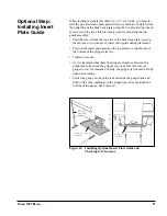
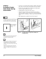
To adjust the photo sensor for proper positioning, follow these steps:
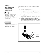
1. Prepare your adjustment by loading the hopper with approxi
-
mately 2 to 2-1/2 in. (5 to 6 cm) of material. Make sure you
preshingle the stack so that material rests against the curvature
of the gate assembly.
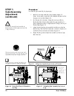
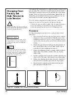
2. Use your finger or thumb on the drive belt or one of the feed
rollers to manually move the bottom sheet of material through
the gate assembly area and under hold-down springs. Con
-
tinue until material leading edge is in-line with front hopper
plate, then stop (Figure 26).
3. Turn the feeder power On by pushing the horizontal line (
—
)
at the
Power
On/Off rocker switch.
STEP 4:
Final Photo Sensor
Adjustment
Standard photo sensor shipped from the factory
is a diffuse reflective detector. No adjustment for
gain is required or necessary.
NO TE
!
Only adjust the photo sensor when the feeder
power is Off. Do not attempt to adjust the photo
sensor while the feeder power is On or while the
feeder is running. Doing so will expose you to
pinch points which can cause injury to hands or
fingers.
Potential damage to feeder parts is avoided if
adjustments are made when the feeder power is
Off.
IMPOR TANT
Observe the overlap between the trailing edge
of the bottom sheet and leading edge of the next
sheet. It should be approximately 1/4 in. (6.4 mm)
to 1/2 in. (12.7 mm). If not refer back to Step 7,
“Align Feeder with Insert Station”, for more
information.
Figure 26. Moving the First Sheet Into Position
Leading edge
rests against
front hopper
plate
!
Summary of Contents for Thiele Technologies Streamfeeder Reliant 1500
Page 1: ...Manual Reliant 1500 ...
Page 12: ...6 Reliant 1500 Manual ...
Page 36: ...30 Reliant 1500 Manual ...
Page 46: ...40 Reliant 1500 Manual ...
Page 49: ...43 Relaint 1500 Manual 8 Electrical Schematics 120V Electrical Schematic ...
Page 50: ...44 Reliant 1500 Manual 240V Electrical Schematic ...
Page 51: ...45 Relaint 1500 Manual 120V Electrical Schematic with Vacuum Select ...
Page 52: ...46 Reliant 1500 Manual 240V Electrical Schematic with Vacuum Select ...
Page 53: ...47 Relaint 1500 Manual 9 Mechanical Components ...
Page 57: ...51 Relaint 1500 Manual ...
Page 59: ...53 Relaint 1500 Manual ...
Page 61: ...55 Relaint 1500 Manual ...
Page 65: ...59 Relaint 1500 Manual ...
Page 67: ...61 Relaint 1500 Manual ...
Page 69: ...63 Relaint 1500 Manual ...
Page 70: ...64 Reliant 1500 Manual ...
Page 71: ......
Page 72: ... 2009 Thiele Technologies Inc Streamfeeder Printed in the USA ...


