INSTALLATION GUIDELINES
32
5. CONNECTION TO THE POWER SUPPLY
IMPORTANT!
THE EXPLOSION-PROOF VERSIONS MAY BE MOUNTED AND CONNECTED TO THE
POWER SUPPLY BY QUALIFIED PERSONS ONLY; THE INSTALLER MUST HAVE
ADDITIONAL KNOWLEDGE ABOUT EXPLOSION PROTECTION.
The following items must be checked before the electric motor can be connected to the mains
power supply:
- that the data on the label correspond to voltage and frequency of the power supply,
- that the explosion protection indicated corresponds to the environment the electric motor will be
operated in (gas group, temperature class),
- that the installation (pipes or cables) is carried out correctly.
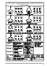
The electric motors rotate clockwise when the phase conductors L1, L2 and L3 are connected to
the terminals U,V,W (1U,1V,1W or U1,V1,W1). Rotation may be changed by switching the
terminals on two phases of conductors.
The following elements are connected to the terminals:
10 – 11 PTC 145°C built in
14 – 15 Thermostats NC (normally closed contact)
16 – 17 Thermostats NO (normally open contact)
The motors are equipped with 3 temperature detectors (PTC thermistor DIN 44081 - ….). These
temperature detectors are to be connected to a tripping unit with one of Ex Notified Bodies mark of
conformity. The tripping unit is not protected against explosions and must therefore be installed
outside of the hazardous area. The mark of conformity serves merely to confirm the adherence to
the electrical data at the interface between the temperature detector circuit and the tripping device
and to allow the application of both the tripping device with mark of conformity and the PTC
contacts according to DIN 44081 for the thermal control of explosion-proof electric machines.
The space heaters are mounted to the terminals 30 – 31 (230V) or 32-33 (110V). Motors with
space heaters are marked with an additional label indicating the nominal data of the heating
system.
The electric control unit must make sure that the nominal motor voltage and the heater voltage are
not present simultaneously.
Take particular care over the connection of the cable cores to the terminal board. The insulation of
the cable cores should be close to the terminal, all wires of the flexible cores must be clamped to
the terminal.
The tightening torque of the connections on the terminal board must not exceed 7,5 Nm.
Pay close attention to the installation instructions when carrying out the explosion protection of the
Ex d terminal box (»explosion-proof enclosure«) and check for the correct explosion protection
cable entry (Ex d entry).
Prior to the mains connection, check the terminal box for the following items:
- there must not be any dust, pieces of wire or other foreign matters inside of the terminal box,
- the electrical connections must be carried out by qualified persons and the screws must be
tightened correspondingly,
- that the mutual air distance is at least 10 mm for voltages of 400 V or 630 V
- that the unused wires are separated and fixed accordingly,
- all joint areas are formly greased with grease type FOR PD-2 (Setral MI PD LL/2A) ali Renolit
RHF-1 Fuchs
-
that the cable is sealed correctly at the cable entry.
-
the unused openings must be sealed so as to
guarantee that the flame-proof properties are
maintained. The means foreseen to achieve this goal must be such so as to ensure that the
Summary of Contents for BM 4KTC71
Page 3: ...3...
Page 4: ...4...
Page 5: ...5...
Page 6: ...6...
Page 43: ...43...
Page 44: ...44...
Page 45: ...45...
Page 46: ...46...
Page 47: ...47...
Page 48: ...48...
Page 49: ...49...
Page 50: ...50...
Page 51: ...51...
Page 52: ...52...
Page 53: ...53...
Page 54: ...54...
Page 55: ...55...
Page 56: ...56...
Page 57: ...57...
Page 58: ...58...
Page 59: ...59...
Page 66: ......
Page 67: ...67...


