
Operational Instruction / DE
2
Information about these instructions
These instructions contain the information required for the
correct use of the installation kit. They are intended for
technically qualified personnel.
The instructions summarise the most important safety
measures and must be read by all those who work with the
product to ensure that they are familiar with its correct use.
The instructions must be held on to and must be available for
the entire service life of the product.
Technical data
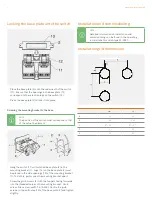
Installation options
For wall thicknesses of between 1 and 5 mm
(0.04 to 0.2 in)
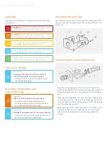
Mounting
- Mounting bracket: by screwing the fixing nut
onto the actuating element
- Base plate: locked into place on the switch and
then screwed to the mounting bracket using
grub screws with adhesive coating
Material
Stainless steel
1.4301 (V2 A), AISI 304
Mass
Approx. 69 g (0.15 lb)
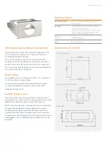
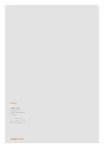
Description
An installation kit for switch type 07-3381-**** is provided
for front mounting in control boxes.
It consists of mounting bracket, base plate and two grub
screws with tappets and coating to secure the screws.
Order No. 05-0091 -0273
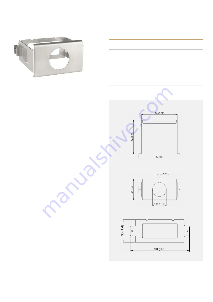
Dimensions in mm (in)
Base plate
Mounting bracket, side view
Mounting bracket
Safety instructions
Use in areas other than those specified or modifications to
the product by someone other than the manufacturer exempts
BARTEC from liability for defects and further liability.
Malfunctions are possible in the event of incorrect installation.
The generally applicable statutory regulations and other
binding directives governing industrial health and safety,
accident prevention and environmental protection must be
complied with. The installation kit may only be used in a clean,
undamaged condition. Modifications and alterations are not
permitted.


