


Operational Instruction / DE
4
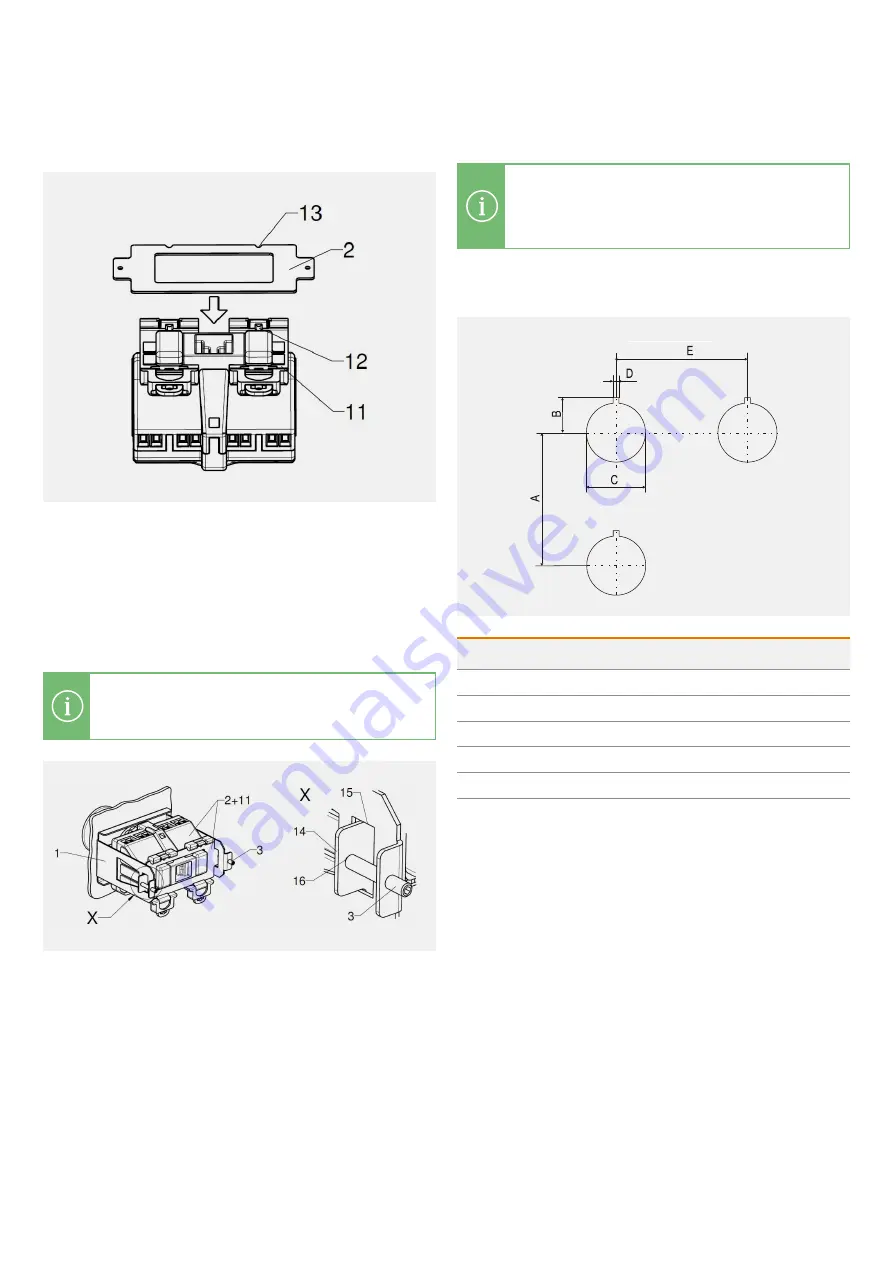
Screwing the mounting bracket to the base
NOTE
The position of the switch must correspond to that
of the actuating element.
–
Hang the switch (11) with latched base plate (2) in the
mounting bracket (1). Lugs (14) on the base plate (2) must
be placed in the side openings (15) of the mounting bracket
(1). To do this, gently prise the mounting bracket apart.
–
Screw the grub screws (3) with the tappets facing forwards
into the threaded holes on the mounting bracket. Grub
screw: Allen screw, width 1.5 (0.059). Centre the grub
screws in the drill holes (16) of the base plate (2) and tighten
slightly.
Installation and commissioning
NOTE
Detailed information on installation and
commissioning can be found in the operating
instructions for switch type 07-3381-...
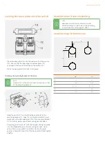
Installation grid dimensions
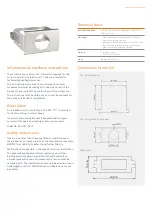
Locking the base plate onto the switch
–
Place the base plate (2) onto the underneath of the switch
(11). Ensure that the openings in the base plate (13)
correspond to the retention lugs on the switch (12).
–
Press the base plate (2) to lock it into place.
mm
in
A
100
3.9
B
16,5
0.65
C
∅
30,3
+0,3
∅
1.9
+0,01
D
3
30
E
100
45


