background image

05-0091-7D0007-10/2019-BARTEC WerbeAgentur-435286

5

Maintenance and troubleshooting   

WARNING! 

Risk of injury due to incorrect procedure. 

-   Maintenance and troubleshooting work may 

only be carried out by authorised, qualified 
personnel. 

Wartung   

WARNING! 

Serious accidents due to damaged components. 

-   Check control switches, position selector 

switches, installation kit and cables regularly 
for tears, damage and to ensure they are 
mechanically secure.

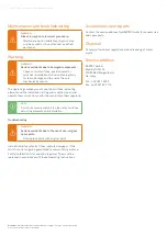
The operating company must keep the switches, actuating 
element and the installation kit in good condition, and must 
operate them correctly, monitor them and clean them regularly. 

Installation kits are faulty if they indicate damage or if the 
switch can no longer be guaranteed to remain firmly in place.  
Faulty installation kits cannot be repaired.  They must be 
replaced in accordance with these Operating Instructions.

NOTE 

Do not use compressed air to clean dirty switches, 
actuating elements and installation.

Troubleshooting

WARNING!

Serious accidents due to the use of non-original 
spare parts. 

-   Only replace parts with original parts.

Accessories, spare parts 

Contact the service address for BARTEC GmbH for accessories 
and spare parts. 

Disposal


Comply with national regulations when disposing of metal 
waste. 

Service address 

BARTEC GmbH  
Max-Eyth-Str. 16   
97980 Bad Mergentheim  
Germany

Tel.: + 49 7931 597 0 
Fax: +49 7931 597 119

Disclaimer: 

We reserve the right to make technical changes.  Changes, errors and printing 

errors do not justify claims for damages.

Summary of Contents for 05-0091-0273

Page 1: ...05 0091 7D0007 10 2019 BARTEC WerbeAgentur 435286 Operating Instructions Installation Kit 05 0091 0273 ...

Page 2: ... with adhesive coating Material Stainless steel 1 4301 V2 A AISI 304 Mass Approx 69 g 0 15 lb Description An installation kit for switch type 07 3381 is provided for front mounting in control boxes It consists of mounting bracket base plate and two grub screws with tappets and coating to secure the screws Order No 05 0091 0273 Dimensions in mm in Base plate Mounting bracket side view Mounting brac...

Page 3: ...minently hazardous situation which if not avoided will result in death or serious injury WARNING indicates a potentially hazardous situation which if not avoided could result in deat or serious injury CAUTION indicates a potentially hazardous situation which if not avoided may reult in death or serious injury ATTENTION indicates a potentially hazardous situation which if not avoided may result in ...

Page 4: ...oles on the mounting bracket Grub screw Allen screw width 1 5 0 059 Centre the grub screws in the drill holes 16 of the base plate 2 and tighten slightly Installation and commissioning NOTE Detailed information on installation and commissioning can be found in the operating instructions for switch type 07 3381 Installation grid dimensions Locking the base plate onto the switch Place the base plate...

Page 5: ...ulty if they indicate damage or if the switch can no longer be guaranteed to remain firmly in place Faulty installation kits cannot be repaired They must be replaced in accordance with these Operating Instructions NOTE Do not use compressed air to clean dirty switches actuating elements and installation Troubleshooting WARNING Serious accidents due to the use of non original spare parts Only repla...

Page 6: ...bartec com BARTEC BARTEC GmbH Max Eyth Str 16 97980 Bad Mergentheim Germany Tel 49 7931 597 0 Fax 49 7931 597 119 Mail info bartec com ...

Reviews: