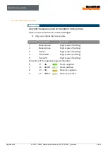
Electrical connections
Ex p control unit
Motor Purge Controller
Page 34 of 96
01-37A2-7D0003_Operating instructions_MPC_20210923_0_en.docx
Rev. 0
Inductive loads
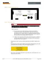
ATTENTION
INTERFERENCES FROM INDUCTIVE LOADS MAY DESTROY THE EXP
CONTROL UNIT.
When switching off inductive loads (e.g. contactor coils), over-voltages
occur. Voltage peaks of up to 4 kV can occur with a voltage gradient of 1 kV /
microsecond.
Use suitable measures to suppress inductive loads.
Use protective circuits with inductive loads to limit the voltage peaks that occur
when switching off.
The consequences could be as follows:
Coupling of interference signals that generate false signals
The Ex p control unit could be destroyed
Protective circuits protect the Ex p control unit from premature failure due to the
overvoltage that occurs when the current flow through an inductive load is
interrupted. In addition, protective circuits limit the electrical interference that
occurs when switching inductive loads.
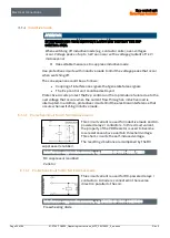
6.1.4.1
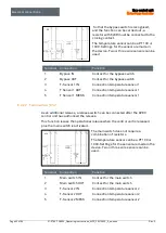
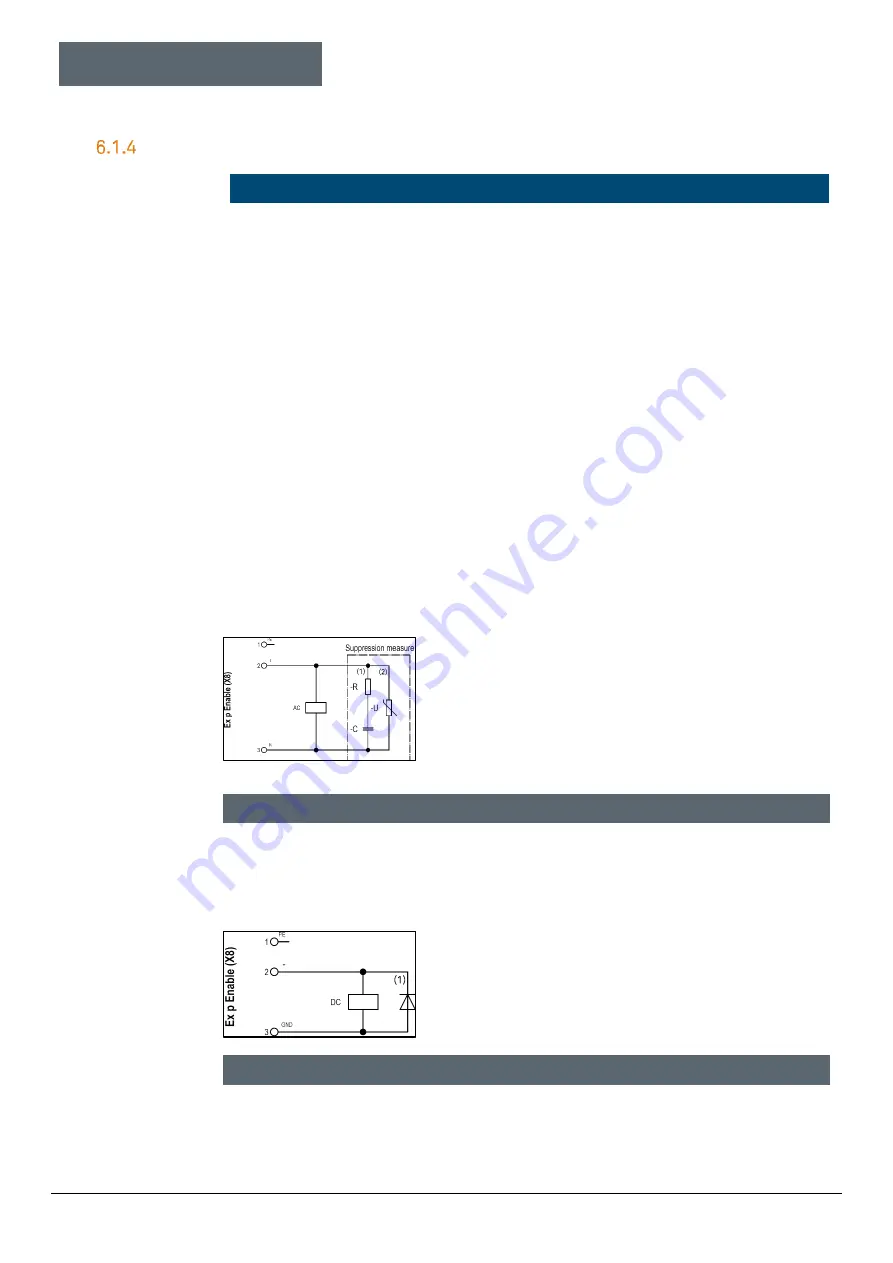
Protective circuit for AC fed inductive loads
This circuit variant is used for inductive loads and AC-
powered relays / contactors. In this circuit variant,
the property of the VDR resistor is used to become
low-resistance above a certain threshold voltage.
This short-circuits the self-induced voltage.
The resulting vibrations are dampened by the RC
suppressor (snubber).
Interference suppression measure, e.g. BARTEC 07-7311-93GU / K000
RC suppressor (snubber)
Varistor
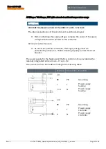
6.1.4.1
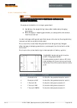
Protective circuit for DC fed inductive loads
This circuit variant is used for DC-powered relays /
contactors. A diode is connected in the reverse
direction parallel to the coil.
Interference suppression measure, e.g. BARTEC 07-7311-61GF/5400
Freewheeling diode


